Beijer Electronics Frequency Inverter BFI-E3 KI00369B 2019-09
www.beijer.se www.beijer.no www.beijer.dk www.beijerelectronics.de www.beijerelectronics.com www.beijerelektronik.com.tr 12 (24)
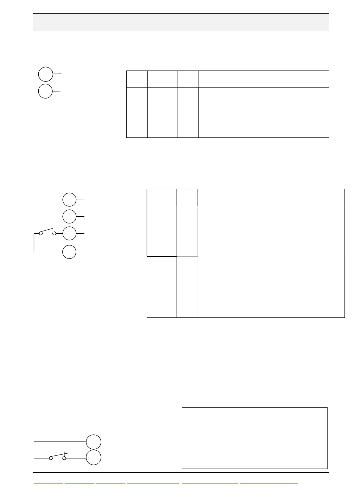
5.7 Analog output, 0-10 VDC
Between terminal 8 and 9 an analog output of 0-10 VDC is generated. Maximum load is 20 mA.
5.8 Digital outputs
Terminal 8 generates 0 or 24 VDC output without any external 24 VDC power supply.
5.9 Styrning av mekanisk hållbroms i motorn
A mechanical brake inside the motor should be controlled directly from the inverter.
If relay output on terminal 10 and 11 is used: Set P-18=4 and frequency release level in
P-19. P-19 is set in % of P-01, Maximum frequency.
If transistor output on terminal 8 and 9 is used: Set P-25=4 and frequency release level in
P-19. P-19 is set in % of P-01, Maximum frequency.
For example if P-01=50: P-19=5 % means break release at 50 x 0,05= 2,5 Hz.
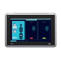
5.10 PTC-thermistor
Para-
Name
Function
P-25
Analog
Output
Function
8
8: Output Frequency: 0 to 100% = 0-10 V => 0 to
P-01 Hz.
9: Output Motor Current: 0 to 200% = 0-10V => 0
to P-08 A.
10: Motor Power: 0 to 200% = 0-
Rated inverter power kW.
11: Load current: 0-200% = 0-10V => 0 till P-08,
Current used producing torque on motor shaft.
Parameter
Function
P-18:
Relay
Output
Function
Terminal
10 and 11
P-18=1
0: Drive Enabled or running.
1: Drive Healthy. Power applied to the drive and no fault.
2: At Target Frequency. Output frequency matches the set
frequency.
3: Drive Tripped and in a fault condition
4: Output Frequency >= Limit. Logic 1 when the output
frequency is > limit set in P-19.
5: Output Current >= Limit. Logic 1 when the motor current is >
limit set in P-19.
6: Output Frequency < Limit. Logic 1 when the output frequency
is < limit set in P-19.
7: Output Current < Limit. Logic 1 when the motor current is <
limit set in P-19.
8: Analog input2 > Limit Logic 1 when analog input2 > P-19 (not
available in P-25).
9: Drive ready to run Logic 1 when BFI is ready to run (not
available in P-25)
P-25:
Analog
Output
Function
Terminal
8 and 9
P-25=8
DI3: External Trip
+24
VDC
0-10 V Output
0 V reference
Relay
Output
8
9
Transistor
Output
Output
10
11
0 V
A motor thermistor, PTC Type 2,5 kΩ, is to be
connected between terminals 1 and 4. BFI will
trip with open contact or a resistance above 2.5
kOhm.
Set P-15=3 and P-47 = “Ptc-th".
Input is not ATEX approved.