Beijer Electronics Frequency Inverter BFI-E3 KI00369B 2019-09
www.beijer.se www.beijer.no www.beijer.dk www.beijerelectronics.de www.beijerelectronics.com www.beijerelektronik.com.tr 19 (24)
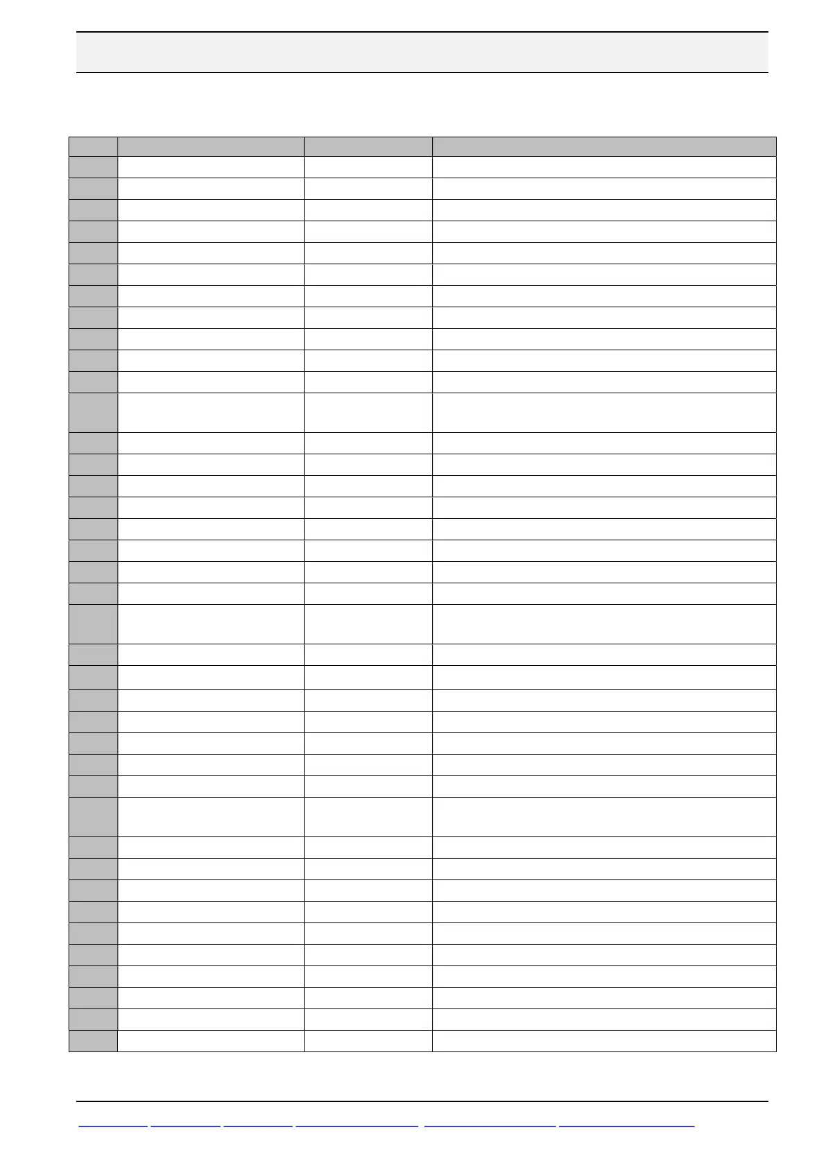
6.1 Monitoring from Keypad
Put P14=201 to access monitor values in parameter group P0.
Par Description Display range Explanation
P0-01
1st Analog Input Value 0 … 100% 100% = max input voltage
P0-02
2nd Analog Input Value 0 … 100% 100% = max input voltage
P0-03 Speed Reference Input -P-01 … P-01 Displayed in Hz if P-10 = 0, otherwise displayed in RPM
P0-04 Digital Input Status Binary value Drive digital input status
P0-05
User PI output (%) 0 … 100% User PI output (%)
P0-06
DC bus ripple (V) 0 … 100% DC bus ripple (V)
P0-07
Applied Motor Voltage 0 … 600V AC Value of RMS voltage applied to motor
P0-08
DC Bus Voltage 0 … 1000V dc Internal DC bus voltage
P0-09 Heatsink temperature -20 … 120 °C Temperature of heatsink in ᵒC
P0-10 Hours Run Meter 0 to 99 999 hours Not affected by resetting factory default parameters
P0-11
Run Time Since Last Trip1 0 to 99 999 hours Run-time clock stopped by drive disable or trip.
P0-12
Run Time Since Last Trip2
0 to 99 999 hours
Run-time clock stopped by drive disable or trip. Not reseted
by power down / power up cycling.
P0-13 Trip Log 0 to 99 999 hours Displays most recent 4 trips with time stamp
P0-15 DC Bus Voltage Log 0 … 1000V 8 most recent values prior to trip, updated every 256ms
P0-16
Heatsink Temperature Log -20 … 120 °C 8 most recent values prior to trip, updated every 30s
P0-17
Motor Current 0 to 2x rated current 8 most recent values prior to trip, updated every 256ms
P0-18
DC bus ripple log (V) 0 … 100% 8 most recent values prior to trip, 22ms sample time
P0-19
Internal drive temperature log -20 … 120 °C 8 most recent values prior to trip, 30 s sample time
P0-20 Internal drive temperature -20 … 120 °C Actual internal ambient temperature in ᵒC
P0-23 Temperature log cooling fin Hours:min Total time of operation above heatsink temp of 85ᵒC
P0-24
Temperatur log internally Hours:min
Total time of operation with drive internal temperatur above
80ᵒC
P0-25
Estimated rotor speed 0 … 500 Hz In vector control modes, estimated rotor speed in Hz
P0-26
kWh meter / MWh meter
0.0 kWh / 0 MWh
Total number of kWh / MWh consumed by the drive.
P0-27
Total run time of drive fans Hours:min:sec First value displays time in hrs, press up to display mm:ss.
P0-28
Software version e.g. “1.00”, “47AE” “1”: Indicates I/O processor, “2“ : Indicates power stage
P0-29
Drive type identifier BFI type, Drive rating, input phases, voltage, firmware
P0-30 Drive serial number xxxxxx / yy / zzz Unique drive serial number
P0-31 Motor current Id / Iq 0 to 2x rated current Displays magnetising current (Id) and torque current (Iq).
P0-32
Actual PWM switching
frequency (kHz)
4 to 32 kHz
Actual switching frequency used by drive
P0-33
Critical fault counter – O-I Number of times Number of trips due to overcurrent
P0-34 Critical fault counter – O-Volts Number of times Number of trips due to over voltage
P0-35 Critical fault counter – U-Volts Number of times Number of trips due to under voltage
P0-36
Critical fault counter – O-temp Number of times Number of trips due to over temperature heatsink
P0-38
Error counter – O-hEAt Number of times Number of trips due to internal over temperature
P0-39
Error counter – Modbus Number of times Number of trips due to Modbus error
P0-47
Fire mode running Hours Hours Number of Hours in Fire mode
P0-48 Scope channel 1 & 2 Displays value for Scope channel 1 & 2
P0-49 Scope channel 3 & 4 Displays value for Scope channel 3 & 4
P0-50
Bootloader and motor control Internal value