Beijer Electronics Frequency Inverter BFI-E3 KI00369B 2019-09
www.beijer.se www.beijer.no www.beijer.dk www.beijerelectronics.de www.beijerelectronics.com www.beijerelektronik.com.tr 4 (24)
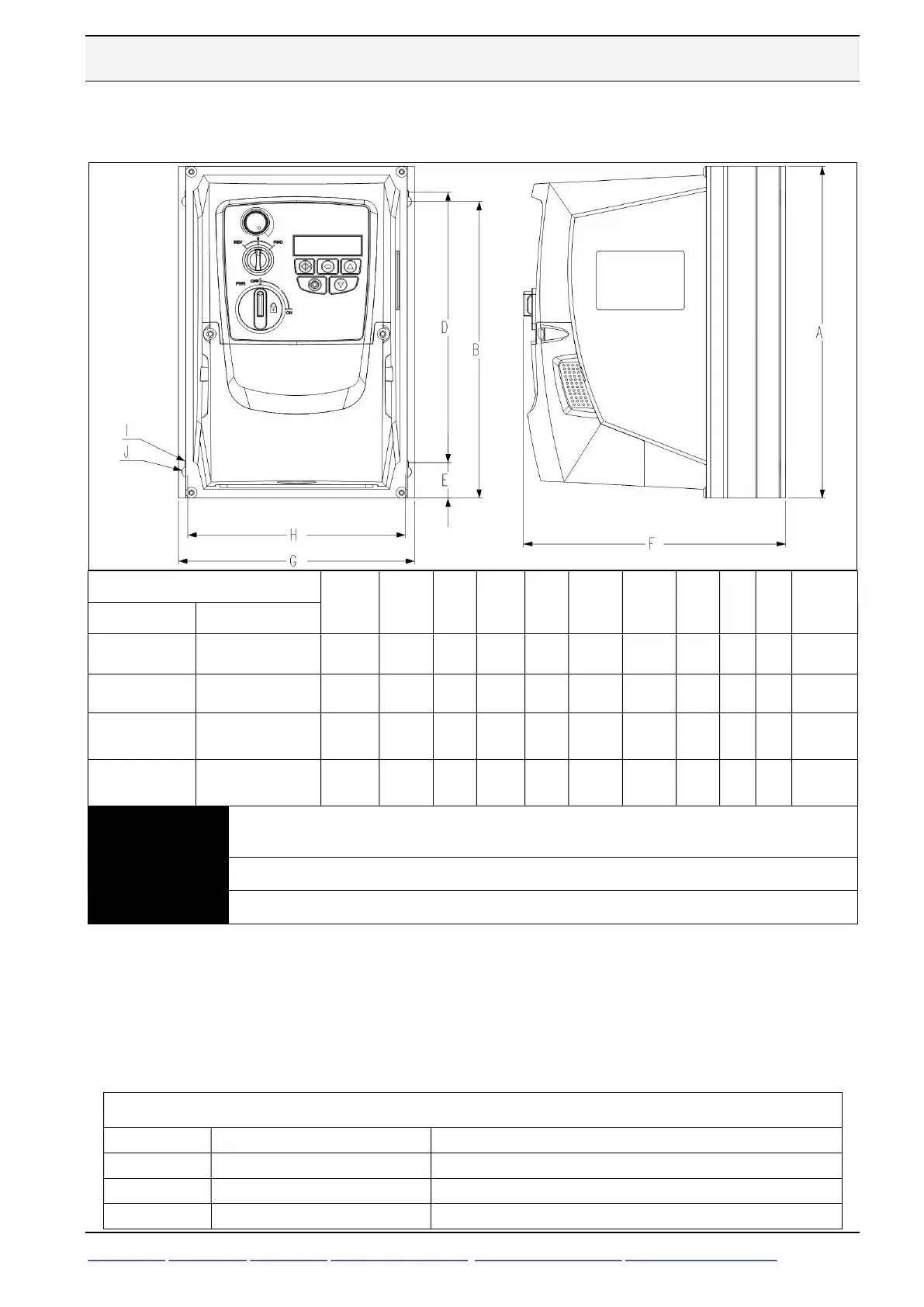
4.2 Physical dimensions IP66
BFI-E3- -IP66
Drive
size
A
Height
[mm]
B
[mm]
D [mm]
E
[mm]
F
Depth
[mm]
G
Width
[mm]
H
[mm]
I
[mm]
J
[mm]
Weight
[kg]
1 x 230 V 3x380-480 V
0023-0070
[0,37-1,5 kW]
0022-0041
[0,75-1,5 kW]
1 232 207 189 25.0 162 161 149 4.0 8.0 2,5
0070-
[1,5-2,2 kW]
0041-0095
[1,5-4,0 kW]
2 257 220 200 28.5 182 188 176 4.2 8.5 3,5
0153
[4,0 kW]
0140-0240
[5,5-11 kW]
3 310 277 251,5 33.4 238 210 197.5 4.2 8.5 7,0
0300-018
[15-18 kW]
4 360 300 33.4 275 240 9,5
NOTE
1x230 V BFI-E3-0070 and 3x400 V BFI-E3-0041 are without brake transistor for Size 1 and Size2
with.
Mounting bolts for Size1 to Size 3 are 4xM4 and 4xM8 for Size 4.
Control Terminal Torque Settings of 0.8Nm. Power Terminal Torque Settings is of 1 Nm.
IP66 drives are fitted with 3 knockout holes for cable inlet and outlet. If more than 3 cables are
to enter the drive it is possible to have two or more cables going through one gland. This is to
ensure IP66.
Holes and recommended glands are listed in table below. The motor cable does not have to be
attached to the drive with an EMC-gland.
Cable Gland, IP66 Hole Size & recommended glands
Hole sizes Gland PG
Size 1
3 x 22mm 3 x PG13,5
Size 2 & 3
1 x 22mm and 2 x 27 mm 1 x PG13,5 and 2 x PG21
Size 4
1 x 22mm and 2 x 40 mm 1 x PG13,5 and 2 x PG29