Beijer Electronics Frequency Inverter BFI-H3 KI00363D 2021-07
www.beijerelectronics.com 13 (32)
Can be set between P1-02(Minimum speed) to P1-01 setting (Maximum
speed)
0: 0 to 10 VDC; 3: 0 to 20mA
4: 4 to 20mA. Trip if signal level < 3mA
5: 4 to 20mA, Ramp to Preset speed 4 if signal level < 3mA
Defines scaling of analog input 1 at maximum analog input value towards
maximum speed in P1-01.
Output frequency= (Analog input value)/100 x (P2-31)/100 * P1-01 [Hz]
P2-32 defines an offset in % of full range for analog input 1.
A positive offset is deducted from the incoming analog signal and a
negative offset is added.
Example, if P2-30=0–10V and P2-32=10.0%, then 1 volt (10% of 10V) will
be deducted from incoming analog reference prior to it being applied.
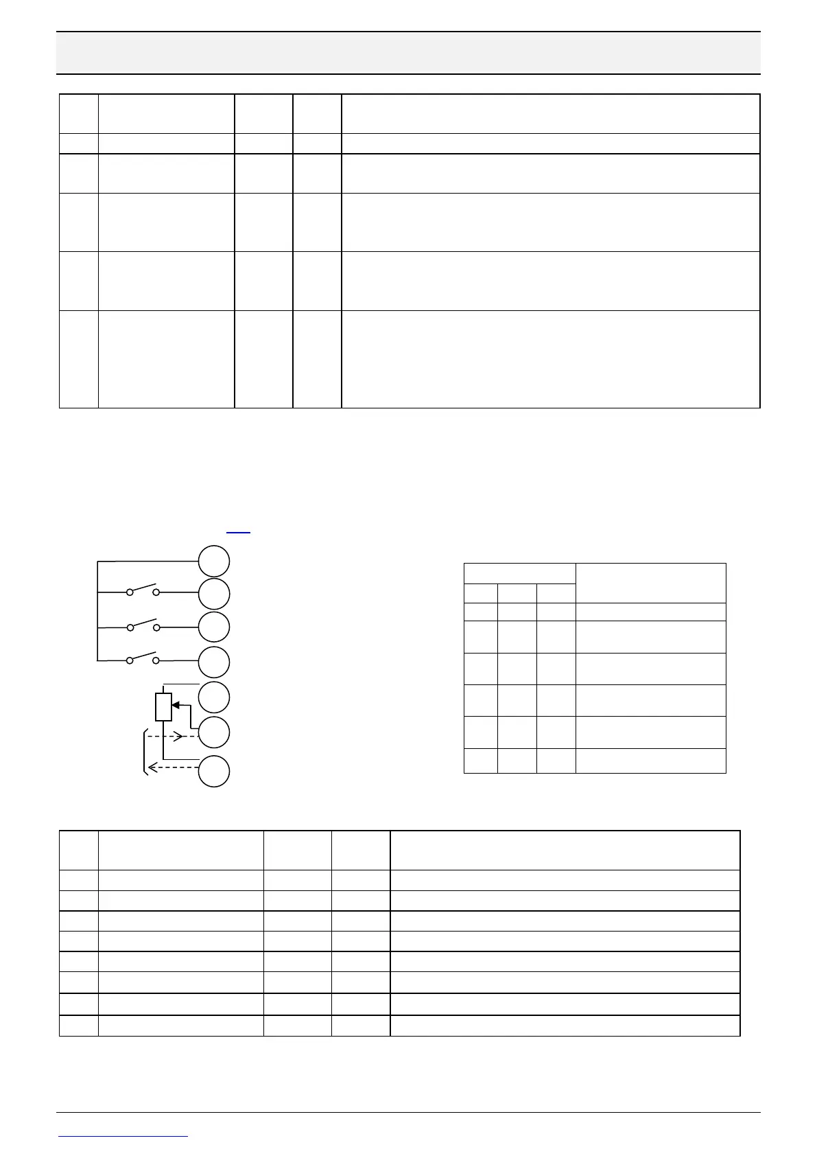
5.2 Digital start in two directions and one Preset or Analog setpoint
Start in forward or reverse direction by digital signal and set frequency is either a fixed preset
speed or analog input signal on terminal 6. Analog input is either 0-10 V or 4-20 mA.
If 4-20 mA signal is used the current should go into terminal 6 and out from terminal 7. For
scaling see chapter 5.1.
0: Open up I/O configuration in Parameter Group 9
Can be set between 0 to P1-01 setting ( Maximum speed)
0: Enable is activated by safety inputs
3: Digital input 3 activates PresetSpeed1
Forward & Analog speed
on terminal 6
Forward & PreSpeed 1 in
P2-01
Reverse & Analog speed
on terminal 6
Reverse & PreSpeed 1 in
P2-01