Beijer Electronics Frequency Inverter BFI-H3 KI00363D 2021-07
www.beijerelectronics.com 15 (32)
5.4 Transistor outputs 24 VDC or analog output, 0-10 V/4-20 mA
Terminal 8 and 11 can be either analog output 0-10 VDC/4-20 mA or transistor output 24
VDC. Outputs do not need an external power supply. Maximum load is 20 mA.
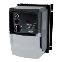
5.5 Relay outputs
0: Drive Enabled or running
1: Drive Healthy. Power is applied to the drive and no fault exists
2: At Target Frequency. Output frequency matches the set frequency
3: Output Frequency > 0 Hz
4: Output Frequency ≥ Limit. Output frequency > P2-16 (AOUT1) or P2-19(AOUT2)
5: Output Current ≥ Limit. Motor current > P2-16 (AOUT1) or P2-19(AOUT2)
6: Output Frequency < Limit. Output frequency > P2-17(AOUT1) or P2-20(AOUT2)
7: Output Current < Limit. Motor current < P2-17(AOUT1) or P2-20(AOUT2)
8: Output Frequency 0-10 V => 0 Hz to setting in P1-01
9: Output Motor Current 0-10 V: 0 to 200% of setting in P1-08
10: Output (Motor) Torque. 0 – 165% of motor rated torque
11: Output (Motor) Power. 0 to 150% of drive rated power
12: PID Output. 0 – 100% represents the output of the internal PID controller
If outputs is to be transistor outputs these parameters do not need to be configured.
0: 0 to 10 VDC; 1: 10 to 0 VDC; 2: 0 to 20 mA;
3: 20 to 0 mA; 4: 4 to 20mA; 5: 20 to 4 mA
P2-15: Relay
output 1
function
terminal 15
and 16
0: Drive Enabled or running
1 Drive Healthy. Power is applied and no fault exists
2: At Target Frequency. Output frequency= Set
frequency
3: Output Frequency > 0.0 Hz
4: Output Frequency ≥ Limit. Output frequency > P2-
16 (Relay1) or P2-19 (Relay2)
5: Output Current ≥ Limit. Motor current > P2-16
(Relay1) or P2-19 (Relay2)
6: Output Torque ≥ Limit. Motor torque current > P2-
16 (Relay1) or P2-19 (Relay2)
7: Analog input 2 > Limit. Analog input 2 > P2-16
(Relay1) or P2-19(Relay2)
8: DOL1 Pump staging – DOL Cascade.
9: Fire Mode Active
10: Maintenance Due
11: Drive available- Ready to run
12: Drive Tripped and in a fault condition
13: Sate Torque off (STO) status
14: PID Error ≥ Limit. The PID Error ≥ Programmed
limit
15: Low and High Current Warning
P2-18: Relay
output 2
function
terminal 18
AOUT1: 0-10 V / 4-20 mA / 24 VDC Default Output Frequency 0-10 V
AOUT2: 0-10 V / 4-20 mA / 24 VDC Default Output Motor Current 0-10 V