Beijer Electronics Frequency Inverter BFI-H3 KI00363D 2021-07
www.beijerelectronics.com 18 (32)
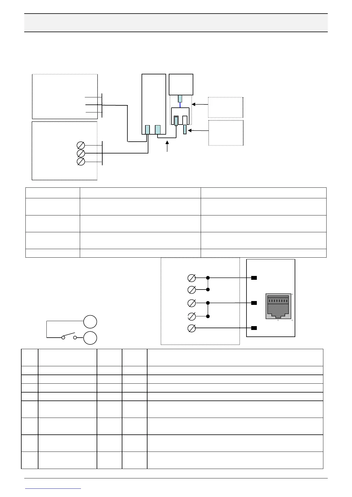
5.9 Control from a Modbus RTU master
BFI IP20/55 has one RJ45 port for Modbus RTU and BFI IP66 two parallel ports. A network with
BFI-E3, BFI-H3 or BFI-P2 is connected as below:
Factorysetting is 115,2 kbit/sec, 8 databits, 1 stop bit, no parity.
Shielded cable with one RJ45 and 3 wires
marked SDA, SDB and SG for screwterminals.
Cable length 3 m. Modbus RTU- pin7 and
Modbus RTU+ pin8 in BFI.
Shielded cable with one RJ45 for BFI and one 9-
pole D-sub for X2 panels.
Cable legth 3 m. Built-in 120 ohm resistor in D-sub
between pin7 and pin8.
T-Connection of 2 serial cables into one drive.
RJ45 male to BFI and 2 female RJ45 for network
connection
RJ45 with a 110 ohm resistor.
To be put in the last BFI-splitter.
4= Control by Modbus RTU.
Get access to all parameter.
Stationnumber 0-63. First Drive should be stationnumber 1
9,6, 19,2, 38,4, 57,6 or 115= kbs
0 or "n-1”= No Parity, 1 stop bit 1 or “n-2”= No parity, 2 stop bits
2 or “0-1”: Odd parity, 1 stop bit 3 or “E-1”= Even parity, 1 stop bit
Drive behaviour if a communication command is not received within time
specified in this parameter. Type of reaction decided in P5-06.
0: Trip and coast to stop 1: Ramp to stop and trip;
2: Ramp to stop and no trip 3: Preset speed 8 (P2-08)
0: Used accelearation- and deceleration time in P1-03 and P1-04
1: Accelearation and deceleration time sent bu Modbus RTU
DI1 must always be closed to start
Use termination of 120 ohm
Modbus master
Nexto Xpress