24 / 172 EN
Split Type Air Conditioner / User Manual
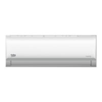
Left rear wall
hole 65mm (2.5in)
144mm (5.65in)
58mm (2.3in)
57mm (2.25in)
Right rear wall
hole 65mm (2.5in)
965mm (38in)
138mm (5.45in)
34mm (1.35in)
Indoor unit outline
517.4mm (20.37in)
Left rear wall hole
65mm (2.5in)
Right rear wall hole
65mm (2.5in)
Indoor unit outline
138mm (5.45in)
517.4mm (20.37in)
144mm (5.65in)
965mm (38in)
34mm (1.35in)
Model C
40mm (1.55in)
58mm (2.3in)
57mm (2.25in)
319mm (12.55in)
221mm (8.7in)
578mm (22.8in)
298mm (11.7in)
Left rear wall
hole 65mm (2.5in)
Right rear wall
hole 65mm (2.5in)
1080mm (42.5in)
54mm
(2.1in)
49mm (1.9in)
79mm(3.1in)
54mm (2.1in)
49mm (1.9in)
149mm
(5.9in)
149mm (5.9in)
138mm (5.4in)
Indoor unit outline
Left rear wall hole
65mm (2.5in)
Right rear wall hole
65mm (2.5in)
Indoor unit outline
221mm (8.7in)
79mm (3.1in)
54mm
(2.1in)
578mm (22.8in)
54mm (2.1in)
298mm (11.7in)
149mm
(5.9in)
149mm (5.9in)
1080mm (42.5in)
138mm (5.4in)
49mm (1.9in)
Model D
49mm (1.9in)
336mm (13.2in)
172mm (6.8in)
362mm (14.25in)
Left rear wall
hole 90mm (3.54in)
Right rear wall
hole 90mm (3.54in)
Model E
1259mm (49.55in)
Indoor unit outline
52mm (2.05in)
389mm (15.3in)
332mm (13.05in)
257mm (10.1in)
643.6mm (25.3in)
52mm (2.05in)
Left rear wall hole
90mm (3.54in)
Right rear wall hole
90mm (3.54in)
Indoor unit outline
52mm (2.05 in)
1259mm (49.55 in)
389mm (15.3in)
643.6mm (25.3in)
257mm (10.1in)
332mm (13.05in)
172mm (6.8in)
52mm (2.05in)
Model E
362mm (14.25in)
C
When the gas side connective
pipe is 16mm(5/8in) or more,
the wall hole should be 90mm
(3.54in).
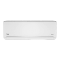
Step 4: Prepare refrigerant piping
The refrigerant piping is inside an insulating
sleeve attached to the back of the unit. You must
prepare the piping before passing it through the
hole in the wall.
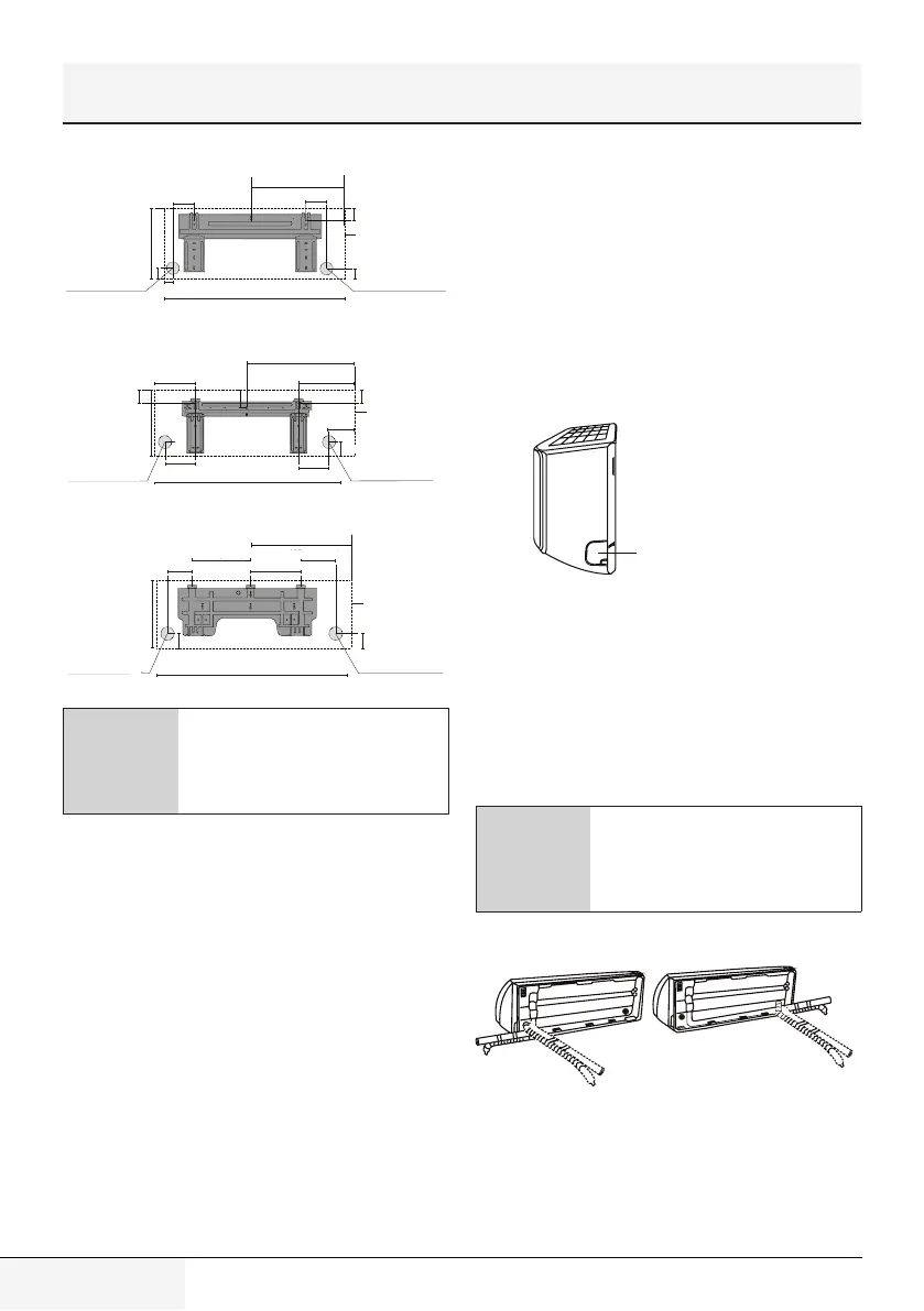
1. Based on the position of the wall hole relative to
the mounting plate, choose the side from which
the piping will exit the unit.
2. If the wall hole is behind the unit, keep the
knock-out panel in place. If the wall hole is to
the side of the indoor unit, remove the plastic
knock-out panel from that side of the unit. This
will create a slot through which your piping can
exit the unit. Use needle nose pliers if the plastic
panel is too difficult to remove by hand.
3. Groove has been made in the knock-out panel
in order to cut it conveniently. The size of the
slot is determined by the diameter of piping.
Knock-out Panel
Knock-out Pancel
4. If existing connective piping is already
embedded in the wall, proceed directly to
the Connect Drain Hose step. If there is no
embedded piping, connect the indoor unit’s
refrigerant piping to the connective piping that
will join the indoor and outdoor units. Refer to
the Refrigerant Piping Connection section of
this manual for detailed instructions.
C
Refrigerant piping can exit the
indoor unit from four different
angles:Left-hand side, Right-
hand side, Left rear, Right rear.
4 Installation
 Loading...