4A1PC-T V2.1 NMV-D2M-EN 11-02-04.doc PM VAV - Subject to technical changes
VAV – Module NMV-D2M
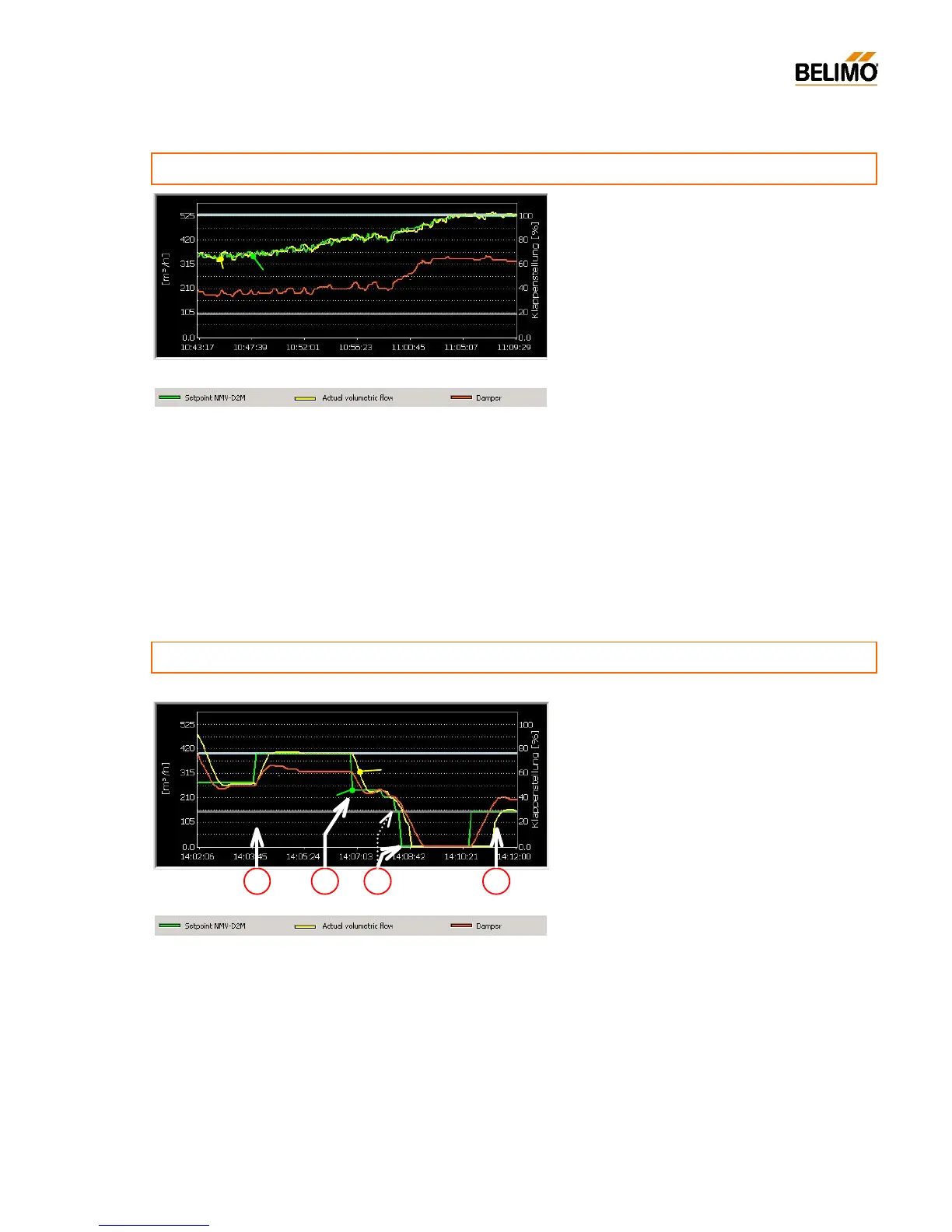
Sequence
- Reference signal hunting
- Volumetric flow following the setpoint
- Damper hunting in the control range
............................................................................................................
unstable reference signal
Suggestions for improvements
Match the reference control circuit correctly and adapt
the controller parameters (P-
complexity of the plant.
Investigate the positioning of the room tempera
sensor. Mounting (e.g. tension from the con
duit),
draughts, sun, etc. can have a direct effect on the
Suitable Test-Sequences
- Test 2 Max-Auto 6m.txt
- Test 3 Max-Auto-Min 9m.txt
-
Record the symptom with ‘Live Trend’ over an extended period of time,
e.g. overnight. This allows intermittent faults to be lo
Note:
The Test-Sequence is discontinued because of the lack of system
supply pressure. Fault alarm: ‘Inadequate supply air pressure’ is given.
Cause and consequence
Room temperature control circuits are usually slow-
response control loops: A tendency to hunt is an
indication of either a lack of settings or incorrect set-
tings.
The VAV controller follows the reference signal, which
is its task. Therefore, when a system is hunt
means that the damper actuator is in con
stant motion.
So an adverse effect on service life is an inevitable
sure control is affected and, as a result, also the
remaining VAV-boxes in the same section.
................................................................................
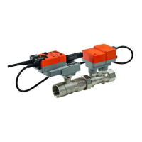
unsuitable reference signal <-> Mode
Sequence
a) Step 1 + 3: V’max / V’min
Function correct
b) Step 2: Auto (reference input active)
- DDC output, room controller: 5.0 V
- NMV-D2M regulates to 245 instead of 275 m
3
/h
c) Step 2: Auto (reference input active)
- DDC output, room controller: 0.0 V
- Damper closes completely instead of to V’min
Suggestions for improvements
a) Change over the NMV-
D2M to the 0...10 V mode,
b) Change over the DDC output, room controller to
working range 2...10 V (if this is possible).
Suitable Test-Sequences
- Test 2 Max-Auto 6m.txt
- Test 3 Max-Auto-Min 9m.txt
Note:
If the system does not attain the required supply pressure – during the
test start – the Test-Sequence is discontinued and the fault alarm ‘In-
adequate supply air pressure’ is given.
Natura lly , the op posi te situ ation c an also ar ise: ‘DDC 2...10 V, NMV-
D2M 0...10 V’.
In this case the result is a worse deviation in the V’min range.
Cause
- The external reference signal (DDC, room tempera-
ture controller) has a working range of 0...10 V
- The NMV-D2M is is set to 2...10 V mode
Function: 0 V = Close
2...10 V = V’min...V’max
The NMV-D2M is closed completely by the 0 V sig-
nal instead of to the required V’min (see c).
a
NMV-D2M – Diagnosis
Legend