25
To install the ruler 12 at an angle, it is necessary to loosen two flywheels 17, install the ruler
along the scale 13 at the desirable angle, and tighten the flywheels 17.
The ruler 12 should to be adjacent to the outfeed 3 table (at any turning angle). It requires
loosening the screws with nuts 11c, moving the ruler along the slots11a of the angular
bumps 11 to the necessary extent, tightening the screws with nuts 11c.
11.1.5 Installing the holding down device
The holding down device is used for workpieces with thickness equal to 5-60 mm.
Install the assembled (p. 10.1.6) holding-down device on the machine as shown the Figure E.
First, install the knife's block fencing 7 with the bracket 8 under the loading planing table 2
(Fig. R)
Before operating the holding down device, it is necessary to set the pressing force of the
workpiece. The pressing force is set by moving the pressure plate up/down.
Loosen the holder 79.
Move the pressure plate, holding its handle, at the height of the workpiece thickness.
Set the appropriate pressing force (so that the workpiece is not detached from the planing
tables and provides a normal pressing force to supply the workpiece to the work zone).
Fix the position of the pressing plate with the help of the holder 79.
11.2 Longitudinal and cross cutting
Before starting, it is recommended to make the following adjustments:
To install tables.
To adjust the cutting depth.
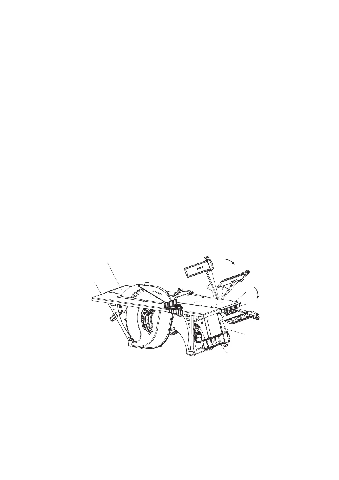
11.2.1 Installing the cutting table
Fig. R
The bracket position with fencing under the loading table
2 – outfeed table; 3 – loading table; 4 – lever-stick, 8 – bracket;7 – knife’s block fencing; 26 – cutting table
To install the cutting table, it is necessary to perform the following:
place the knife's block fencing 8 under the loading planing table 2. To do so, unscrew the
flywheel 19 (Fig.Е), fixing bracket, and place them under the table 2 (Fig. R) by turning the
bracket with fencing around the axis;
bring together the loading 2 and outfeed planing 3 tables, install them on the same level
26
7
8
3
2
4