10 Bend-Tech Dragon
Material Coolant System Assembly
02
Material Coolant System Assembly Manual
2.2 Coolant Tray Components
The coolant trays are placed at the Head of the machine. The coolant trays serve as both parts
catcher and coolant drainback system for the coolant system. Before beginning assembly,
ensure that all components for the coolant trays are present. The coolant Trays consists of:
• Aluminum Trays (3)
• Aluminum Support Legs (3)
• Parts Catcher (1)
• Support Leg Braces (6)
• Parts Rollers (3)
• Leveling Feet (6)
• C Bracket (1)
2.2.1 Parts Catcher and Support Leg Removal
It will be necessary to remove the parts catcher, parts tray, and support leg from the Beak
remove the four screws that hold the parts catcher at the front and back end of the Beak.
Remove the eight screws that hold the parts tray where the Beak mounts to the Head of the
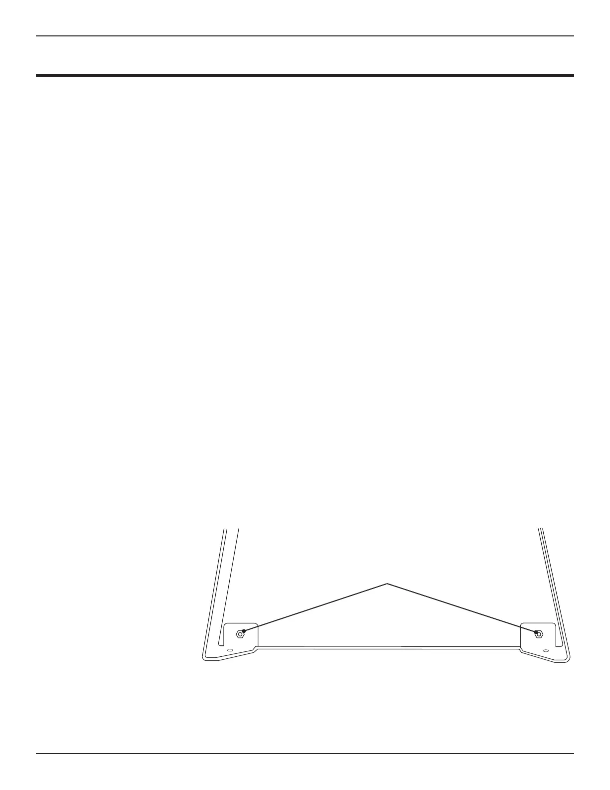
2.2.2 Support Leg Gusset
The bottom of each support leg is constructed with an integrated gusset design. In each
corner, secure the gusset using a 1 in. Button Head Hex Screw, washers and nut. Place a
washer on the 1 in. Button Head Cap Screw and insert into the hole in the Support Leg and
gusset. Place a washer on the inside and thread a nut onto the Button Head Cap Screw. Use
and ratchet to tighten
the nut, securing the
gusset.
1 in. Button Head
Cap Screw

 Loading...
