CC613 charge controller
4 Connection
Connection conditions
DANGER
System parts may be live
(charge controller terminals up to 230 V, charging station 400 V)
Electric shock
Before touching system parts, ensure that it has been de-energised.
CAUTION
Sharp-edged terminals
Cut injuries
Handle enclosure and terminals with care.
Information:
•
PE is connected to "0V"; reference level for Control Pilot (CP communication) must be at the same level
as the power supply (IEC 61851 series of standards).
•
The Ethernet shield is directly connected to PE.
•
The charge controller is supplied with power from a 12 V main voltage source at the +12V and 0V
connections.
•
Lay lines only inside the wallbox and not in parallel with power cables.
•
Connect external Modbus to terminal block I using a shielded cable.
•
External Modbus must be terminated by the customer with a terminating resistor of 120 Ω.
•
Cable lengths (except Modbus, Ethernet, Power IN and charging cable): < 3m.
•
Maximum cable length Ethernet/Fast Ethernet: 100m.
•
Maximum cable length Modbus: 250m.
For further information on connection, refer to the manuals of the accessories
(Example CTBC17P-03).
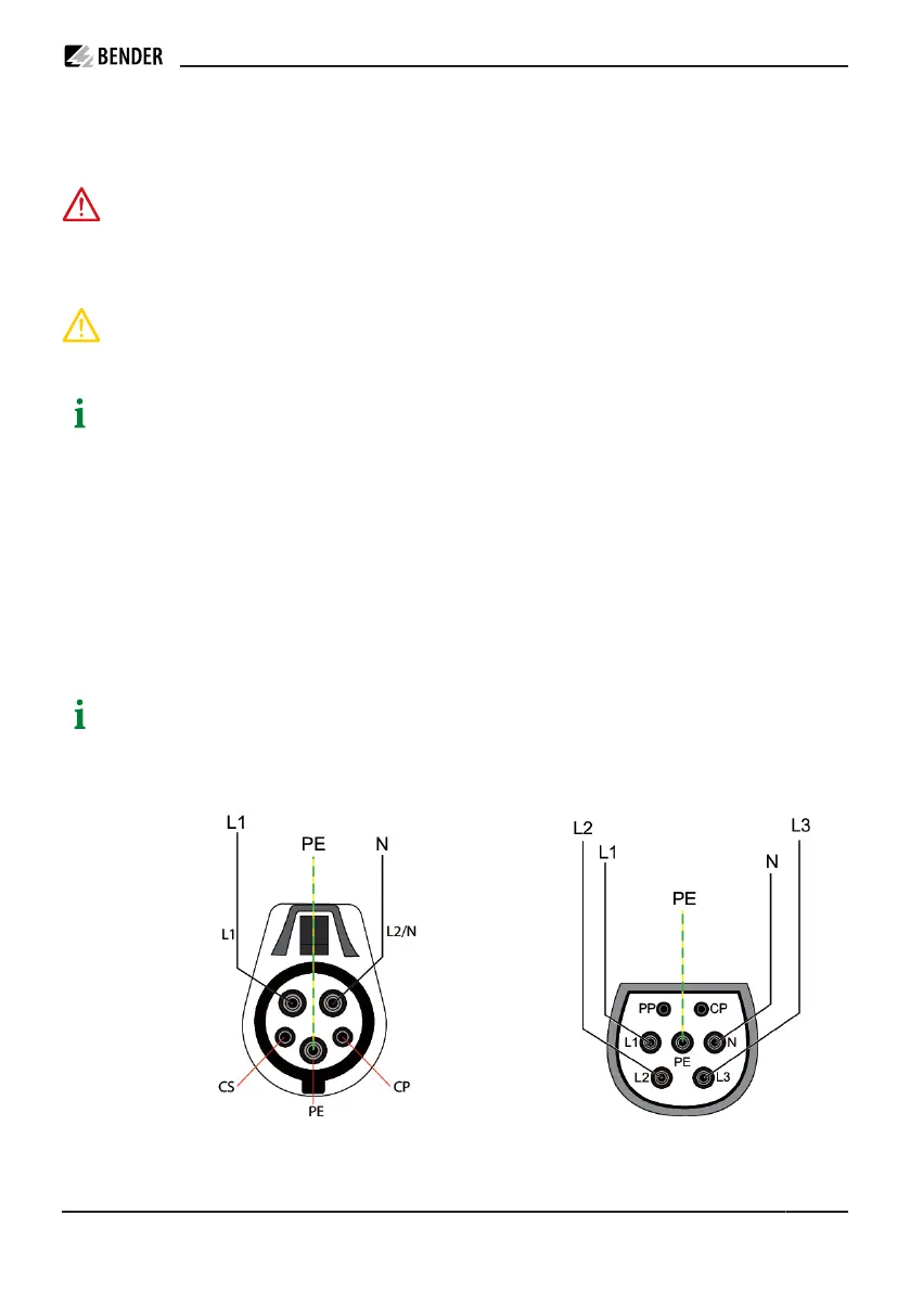
4.1 Connection plug connections
Image: Connection type 1 plug
Image: Connection type 2 plug
CC613_D00381_07_M_XXEN/02.2023 13