CC613 charge controller
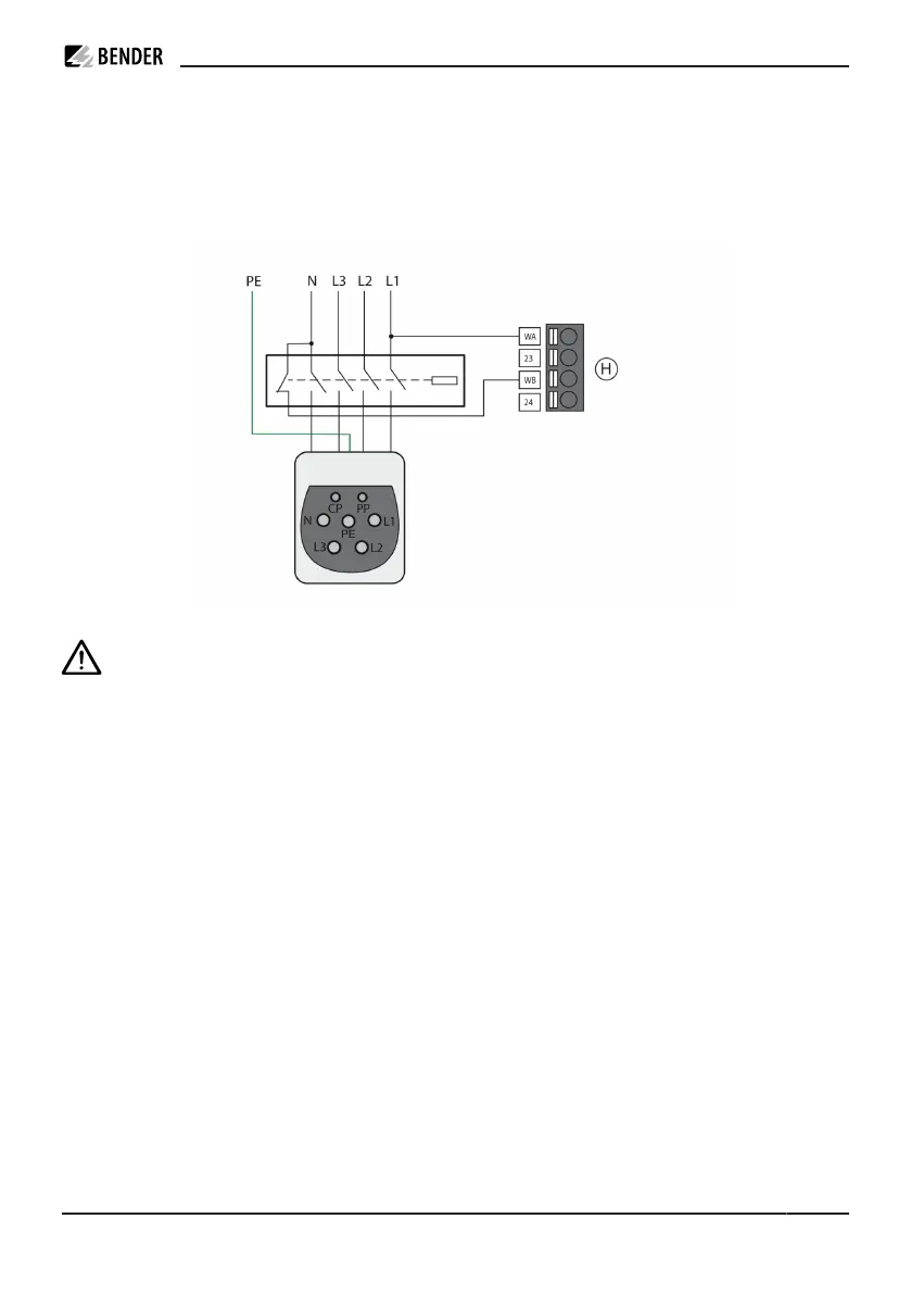
Weld check
By means of the measuring lines (terminal H: WA, WB) impermissible closing of the contactor contacts, e.g.
welding/sticking, can be detected.
Wiring diagram
ADVICE
Risk of a short circuit! For the coupling of terminals WA and WB, devices for protection against a
short circuit can be omitted in accordance with DIN VDE 0100-430 if the wiring is carried out in
such a manner as to reduce the risk of a short circuit to a minimum. (Short-circuit-proof and earth-
fault-proof wiring is recommended). The connecting lines WA and WB to the power supply system
to be monitored must be designed as spur lines. No load current may be conducted through the
terminals.
4.3.4 PE monitoring
PE monitoring
PE monitoring checks whether there is a connection from the charge controller to PE. For this purpose,
WA must be connected to L1. Due to the capacitance of the supply line, the supply line length that can
be checked is limited. To ensure correct functionality of the PE monitoring, L1 must be tapped behind the
measuring current transformer and before the power contactor.
CC613_D00381_07_M_XXEN/02.2023 19