iso415R-x_D00401_00_M_XXEN / 04.2021 15
ISOMETER® iso415R
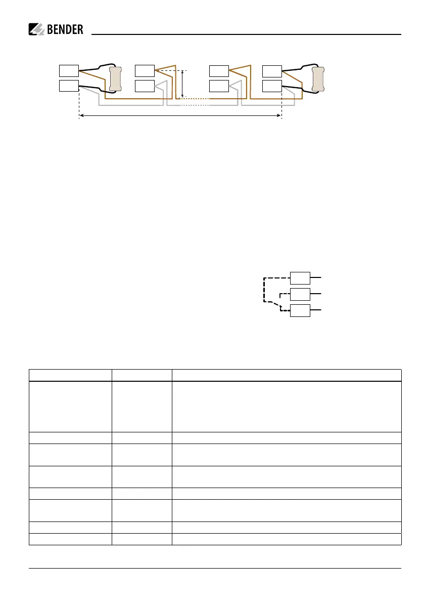
3.2.1.2 RS-485 interface
B
A
B
A
B
A
B
A
max. 1 m
120 Ω
120 Ω
Specification
The RS-485 specification restricts the cable
length to 1200m and requires a daisy chain
connection.
A twisted-pair, shielded cable must be used as
bus cable. For example, cable type J-Y(St)Y
nx2x0.8 mm² is suitable. The shield must be
connected to PE at one end.
Termination
The bus cable must be terminated at both ends
with resistors (120 Ω, > 0.25 W). The terminat-
ing resistors are connected in parallel to the
terminals A and B.
i
If there are more than 16 bus devices, the
interface must be designed to be shock-
proof, because the maximum permissible
total leakage current of 0.5 mA is exceed-
ed.
3.2.1.3 Relay
The terminals 11,14,12 are relay outputs. The
following settings can be made via the Modbus
RTU interface:
i
Caution! High contact currents damage
the hard gold plating of the relay con-
tacts. Damaged contacts prevent the re-
lay from switching correctly at low con-
tact currents.
S2
L1 L2 L3 N
Verbraucher
Load
S1
A1
U
S
~/+ ~/–
A2
RS-485
B
A
–
(+24 V) optional
+
11
14
12
Function State Description
Relay mode NO principle |
NC principle
The relay mode can be adapted to the application:
• N/C NC operation of the contacts 11-14-12. In fault-free condition,
the alarm relay is energised.
• N/O NO operation of the contacts 11-14-12. In fault-free condition,
the alarm relay is de-energised.
Test on* | o This parameter determines whether the relay is actuated during a test
Main alarm on* | o The relay switches when the measured value falls below the response value of the main
alarm AL2
Prewarning on | o* The relay switches when the measured value falls below the response value of the prewarn-
ing AL1
Device error on* | o The relay switches if a device error exists
Connection fault
system
on* | o The relay switches when there is a system connection fault (L1, L2).
Connection fault earth on* | o The relay switches when there is a connection fault to earth (E, KE).
C
e
exceeded on* | o The relay switches when the permissible system leakage capacitance C
e
is exceeded.
* Factory setting