16 iso415R-x_D00401_00_M_XXEN / 04.2021
Operation and settings on the device
4 Operation and settings on the device
4.1 Control panel iso415R
4.1.1 STATUS LED
Multicoloured display of various operating modes.
T / R
Ran2 (kΩ)
Ext 700 400
200
100
70
40
20105
Ran1 (kΩ)
Ext 1k 700
400
200
100
70
1k
100
10
1
kΩ
2
AL
1
ON
AC/DC
k
Ω
L1
L2
E
L1´
L2´
KE
11 12 14
BA-+
A
B
C
D
E
F
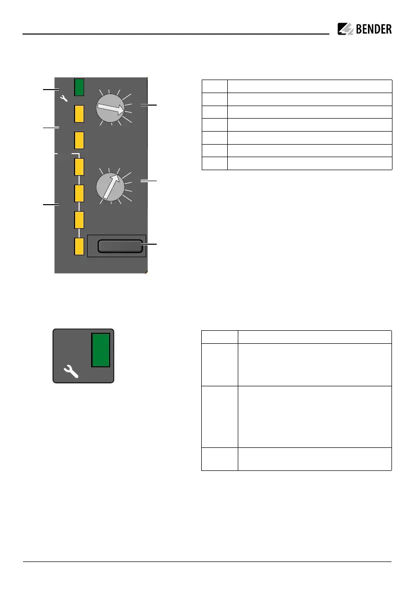
Control panel
A STATUS LED ON – operating modes
B ALARM LEDs – AL1 / AL2
C VALUE DISPLAY LEDs – 1, 10, 100, 1k kΩ (1k = 1000 kΩ = 1 MΩ)
D DETENT POTENTIOMETER 1 – Response value prewarning R
an1
E DETENT POTENTIOMETER 2 – Response value main alarm R
an2
F T/R BUTTON – Test/Reset
i
To confirm a new detent potentiometer positi-
on, the new position is output for a few seconds
as a binary code (1= left stop, 10 = Ext) via the
value display LEDs. The LED "1k" is the least sig-
nificant bit (LSB).
iso415R
T / R
Ran2 (kΩ)
Ext 700 400
200
100
70
40
20105
Ran1 (kΩ)
Ext 1k 700
400
200
100
70
402010
1k
100
10
1
kΩ
2
AL
1
ON
AC/DC
k
Ω
L1
L2
E
L1´
L2´
KE
11 12 14
BA-+
LED Operating mode
GREEN START PHASE
Device booting after start
NORMAL OPERATION
Device in fault-free state
YELLOW
flashing
with val-
ue display
LED
CONNECTION FAULT
• System leakage capacitance C
e
exceeded: LED "10"
ashes
• Connection fault system(L1/L2): LED "100" ashes
• Connection fault earth (E/KE): LED "1k" ashes
RED DEVICE ERROR
Restart or replacement of the device required.