Operation and setting
16
TGH1442en/06.2012
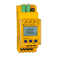
5.2 Function of the operating elements
Device front
Ele-
ment
Function
ON,
green
Lighting continuously: Power On
Flashing:
system fault or connection monitor-
ing fault
AL1,
AL2
LED Alarm 1 lights (yellow):
Response value 1 reached
(I
Δn1
)
LED Alarm 2 lights (yellow):
Response value 2 reached
(I
Δn2
)
13 mA
M
13 mA flow through the measuring
current transformer,
fault memory active
T,
Test button (> 1.5 s):
to indicate the display elements in
use, to start a self test;
Up key (< 1.5 s):
Menu items/values
R,
Reset button (> 1.5 s):
Deleting the fault memory;
Down key (< 1.5 s):
Menu items/values
MENU,
MENU key (> 1.5 s):
Starting the menu mode;
Enter key (< 1.5 s):
Confirm menu item, submenu item
and value.
Enter key (> 1.5 s):
Back to the next higher menu level.