11
STEP FOUR
( Power Console / Hose Routing )
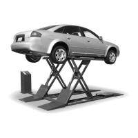
1. Remove the front Panel cover on the Power Console.
2. Route the Hydraulic Hoses and the Air Line through the
holes at the back of the Power Console. (See Fig. 4.1)
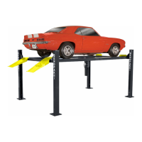
3. Connect the Power Unit (shortest) Hydraulic Hose to
the Power Unit Fitting as shown below. It is not necessary
to use Tefl on tape on JIC fi ttings. DO NOT OVERTIGHTEN.
(See Fig. 4.2)
4. Install the two 90° Fittings and one Straight Fitting in
the Flow Divider confi gured as shown. (See Fig. 4.3 ).
5. Install the Flow divider in the bottom of the Power
Console.
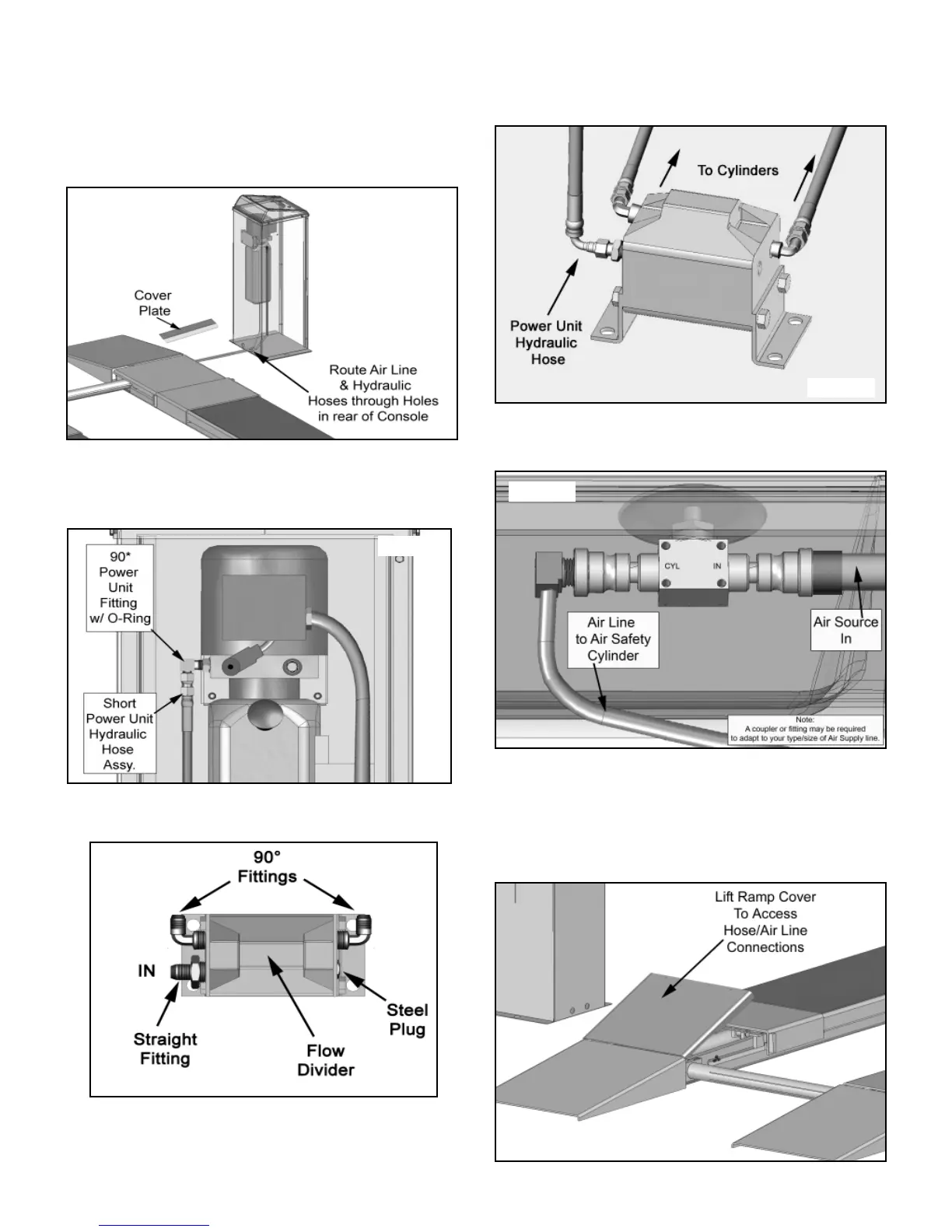
6. Connect the Power Unit Hose to the Straight Fitting on
the Flow Divider and connect both the Powerside and
Offside Hydraulic Hoses to the 90° Fittings on the Flow
divider as shown. (See Fig. 4.4)
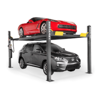
7. Route the 1/4” Poly-Flow Air Tubing through the hole at
the back of the Power Console and connect to the Push
Button Air Safety Switch as shown below. (See Fig. 4.5)
STEP FIVE
( Hose Connections )
1. Raise the Rear Ramp Covers on the lift to access the
Hydraulic Hose/Cylinder connection location. (See Fig. 5.1)
Fig. 4.1
Fig. 4.2
Fig. 4.3
Fig. 4.4
Fig. 4.5
Fig. 5.1