20
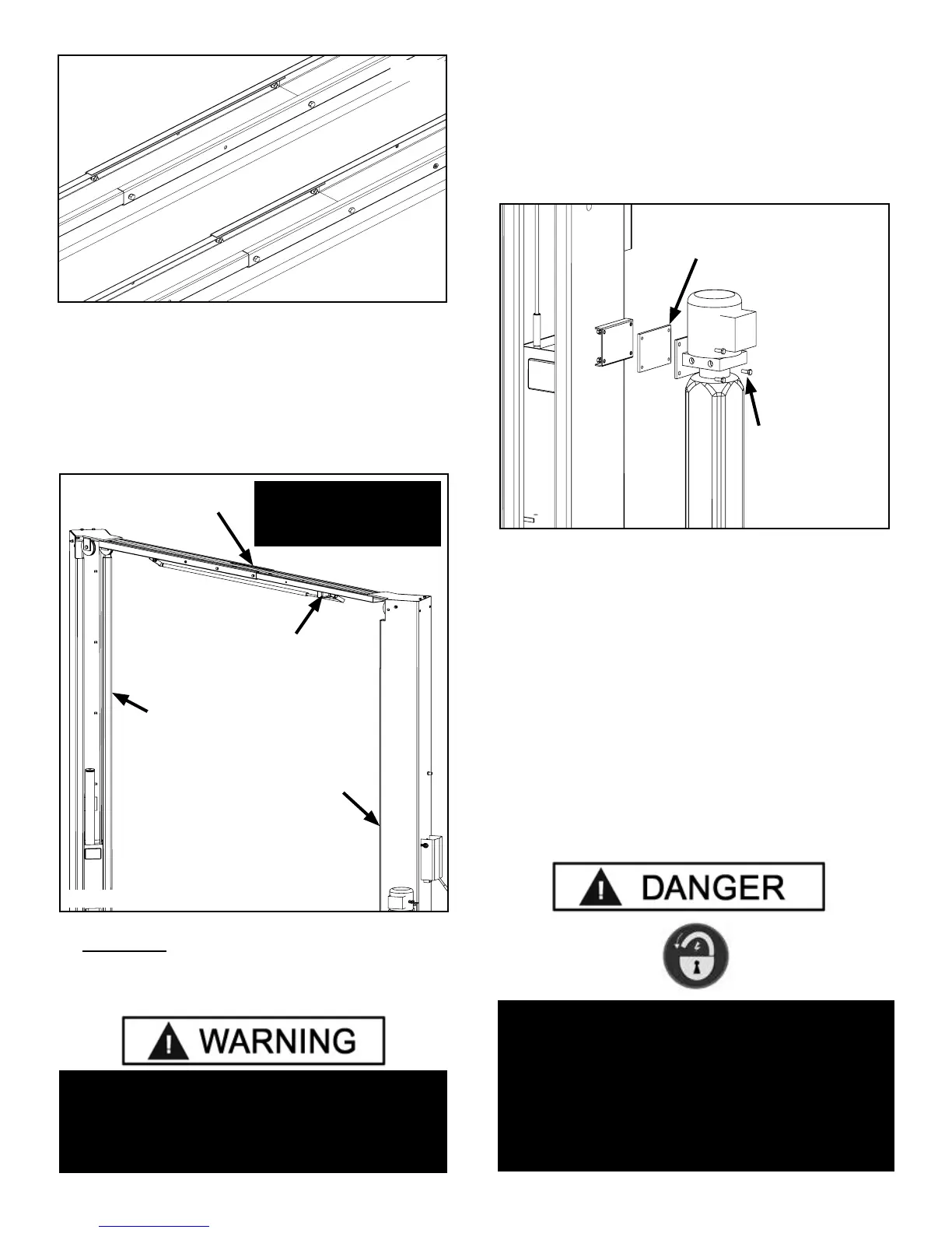
2. Adjust the Overhead Assembly width to match either
the Narrow or Wide conguration, and loosely tighten bolts.
(See Fig 7.1)
3. Using a lifting device, raise the Overhead Assembly
into position on top of the posts. Bolt Overhead Assembly
to the posts using the provided M10 hex head bolts, nuts
and washers.
4. YOU MUST POSITION THE SWITCH ENCLOSURE
ADJACENT TO POWER SIDE POST. (See Fig. 7.2)
5. Tighten the Overhead Assembly bolts.
STEP 8
(Mounting the Hydraulic Power Unit)
1. Attach the power unit to the POWER SIDE post. Install
the vibration dampener between the power unit and the
power unit mounting plate on the Power Side post, using
four M8 hex head bolts and nuts supplied. (See Fig 8.1)
2. Fill the reservoir with 10 WT. HYDRAULIC OR
APPROVED ATF FLUIDS SUCH AS DEXRON III,
DEXRON VI, MERCON V, OR MERCON LV (another
option ISO-32 grade) approximately four gallons. Make
sure the funnel used to ll the Power Unit is clean. Do
not connect power unit hydraulic hose assembly at this
time.
3. The standard power unit for your lift is 220 volt, 60HZ,
single phase. All wiring must be performed by a certied
electrician only. SEE WIRING INSTRUCTIONS AFFIXED
TO MOTOR FOR PROPER WIRING INFORMATION.
STEP 9
(Installing the Safeties and Safety Cable)
20
IF THE ANCHOR BOLTS WERE LOOSENED TO AID
ON THE INSTALLATION OF THE TOP TROUGH,
TIGHTEN ANCHOR BOLTS AS INDICATED
IN STEP 5 ITEMS 4 - 7.
Fig 7.1
Narrow Conguration
Wide Conguration
Fig 7.2
Off Side Post
Power Side Post
Overhead Assembly
Microswitch Bracket
Fig 8.1
Vibration Dampener
M8 x1.25 x 35mm
hex head bolts, M8
at washers and
M8 Nylock nuts
(Qty 4 ea.)
Position Overhead Assembly
with microswitch bracket
adjacent to Power Side post.
DO NOT PERFORM ANY MAINTENANCE OR
INSTALLATION OF ANY COMPONENTS
WITHOUT FIRST ENSURING THAT ELECTRICAL
POWER HAS BEEN DISCONNECTED AT
THE SOURCE OR PANEL AND CANNOT BE
RE-ENERGIZED UNTIL ALL MAINTENANCE
AND/OR INSTALLATION
PROCEDURES ARE COMPLETED.