1414
STEP 3
(Post Preparation)
COMPLETE THE FOLLOWING
PRIOR TO RAISING THE POSTS
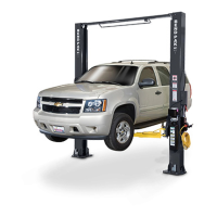
1. Prior to raising posts, slide each carriage upwards to
aid in sheave removal and equalizer cable routing.
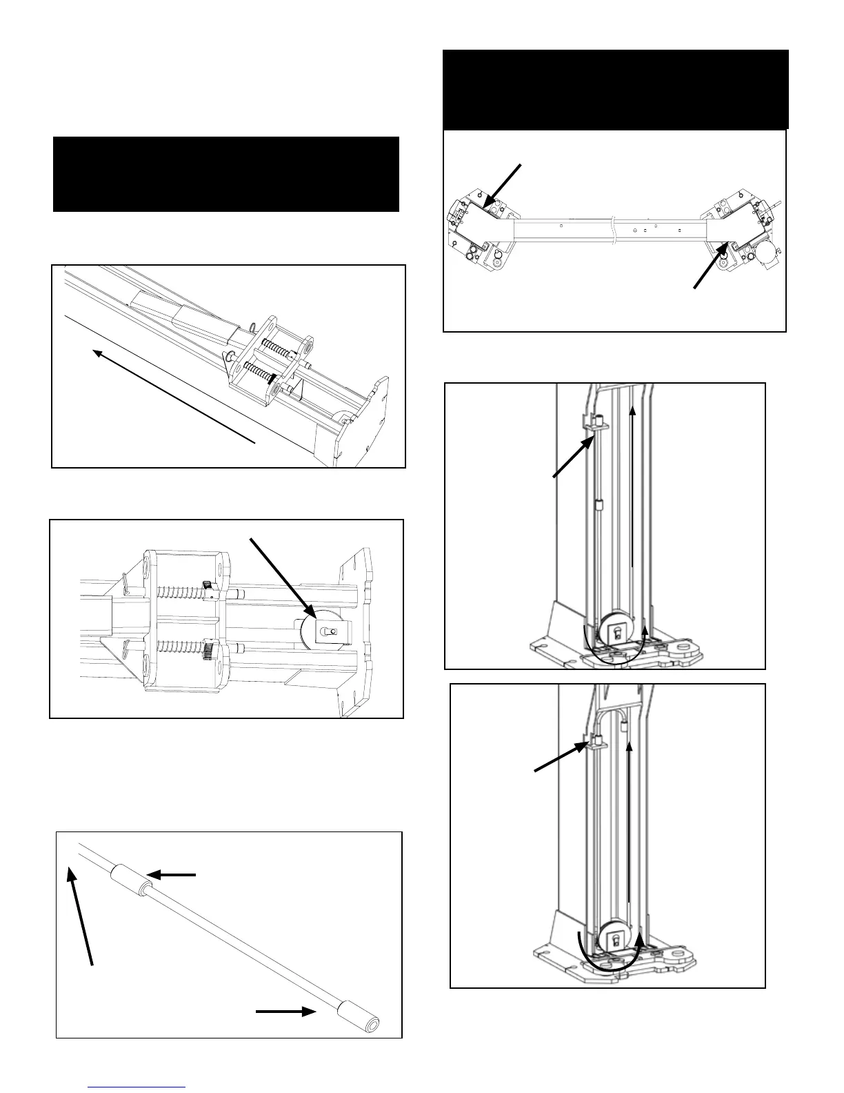
2. Remove the cable sheaves located at the inside
bottom of each post.
3. Identify the correct cable button on the end of each
equalizer cable that corresponds to your desired lift
conguration. Route the button around the bottom sheave
and secure at the carriage lock plate located inside each
carriage.
4. Route threaded end of cable upwards through the
bottom of the carriage. Leave excess cable resting on top of
carriage until further steps are required. (See Fig 3.5)
Fig 3.4
NOTE:
DETERMINE DESIRED LOCATION AND WIDTH
LAYOUT BEFORE RAISING POSTS. REFER TO
LAYOUT CHARTS ON PAGE 12.
NOTE:
SYMMETRICAL MODELS BOTH CABLES ARE SAME
LENGTH. ASYMMETRIC MODELS HAVE TWO
DIFFERENT LENGTH CABLES. (SEE FIG. 3.4)
Fig 3.5
Slide carriage
upwards
Remove cable sheaves
For narrow conguration
For wide conguration
To threaded
cable end
For Asymmetric Models Only
Long cable on lock plate
THIS SIDE
Short cable on lock plate
THIS SIDE
For Wide
conguration,
lock cable button
into second
button position
into Lock Plate
inside of the
carriage.
Threaded
end of cable
routed up
through
carriage
towards
Overhead
Assembly.
NOTE: Portions of Carriage and Post cut away for clarity
Fig 3.3
Fig 3.2
Fig 3.1
Fig 3.6
Threaded end of
cable routed up
through carriage
towards Overhead
Assembly.
For Narrow
conguration,
lock cable
button into rst
button position
into Lock Plate
inside of the
carriage.
NOTE: Portions of Carriage and Post cut away for clarity
NOTE: Second Cable Button should be tucked away from
the lifting cable route. Second Cable Button in Fig 3.6
shown for representational purposes only.