1111
STEP 4
(Site Layout)
1. Determine which side will be the approach side.
2. Now determine where the Power Unit will be located.
The POWERSIDE column has the power-unit mounting
bracket attached to the side.
3. Once a location is determined, use a carpenters chalk
line to layout a grid for the Post locations. Keep all
dimensions and squareness within 1/8” or malfunctioning of
the lift can occur. (See page 11)
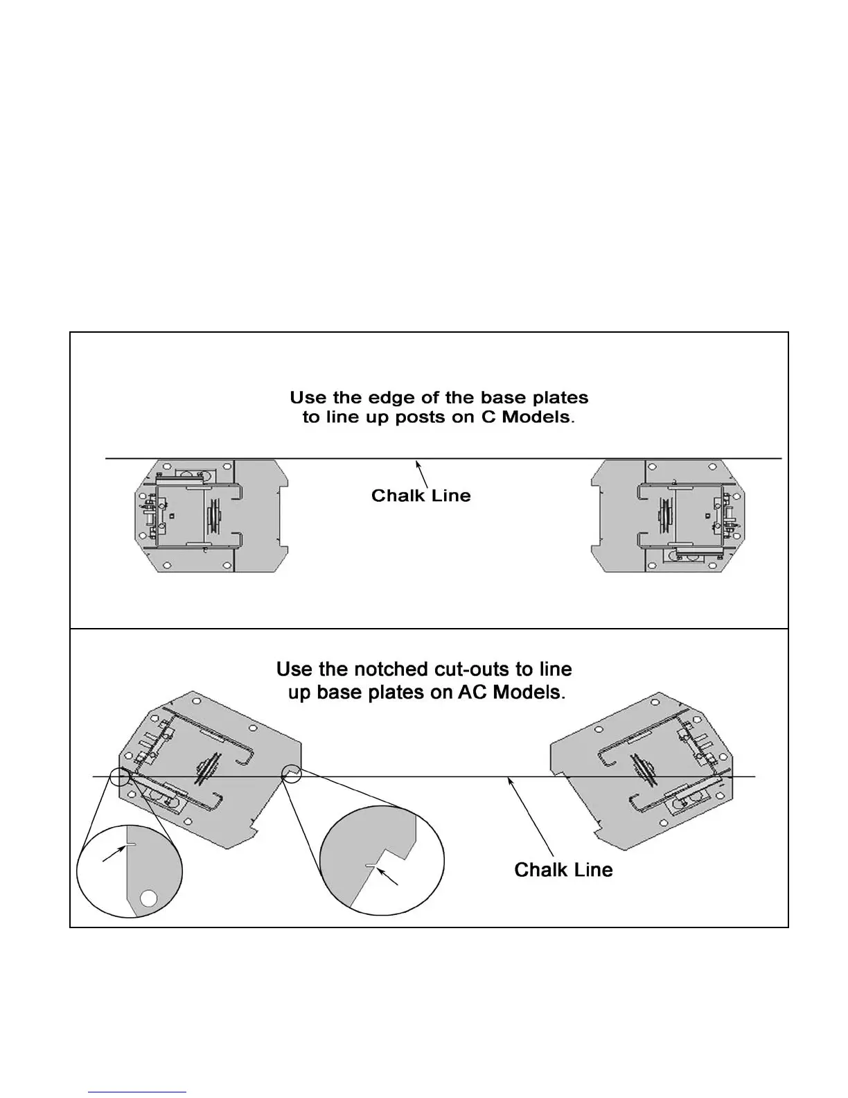
4. After the Post locations are properly marked, use a
chalk or crayon to make an outline of the Posts on the floor
at each location using the Post Base Plates as a template.
(See Fig 4.1)
5. Double check all dimensions and make sure that the
layout is perfectly square.
Fig 4.1.