10
STEP 4
( Site Layout )
1. Determine which side will be the approach side.
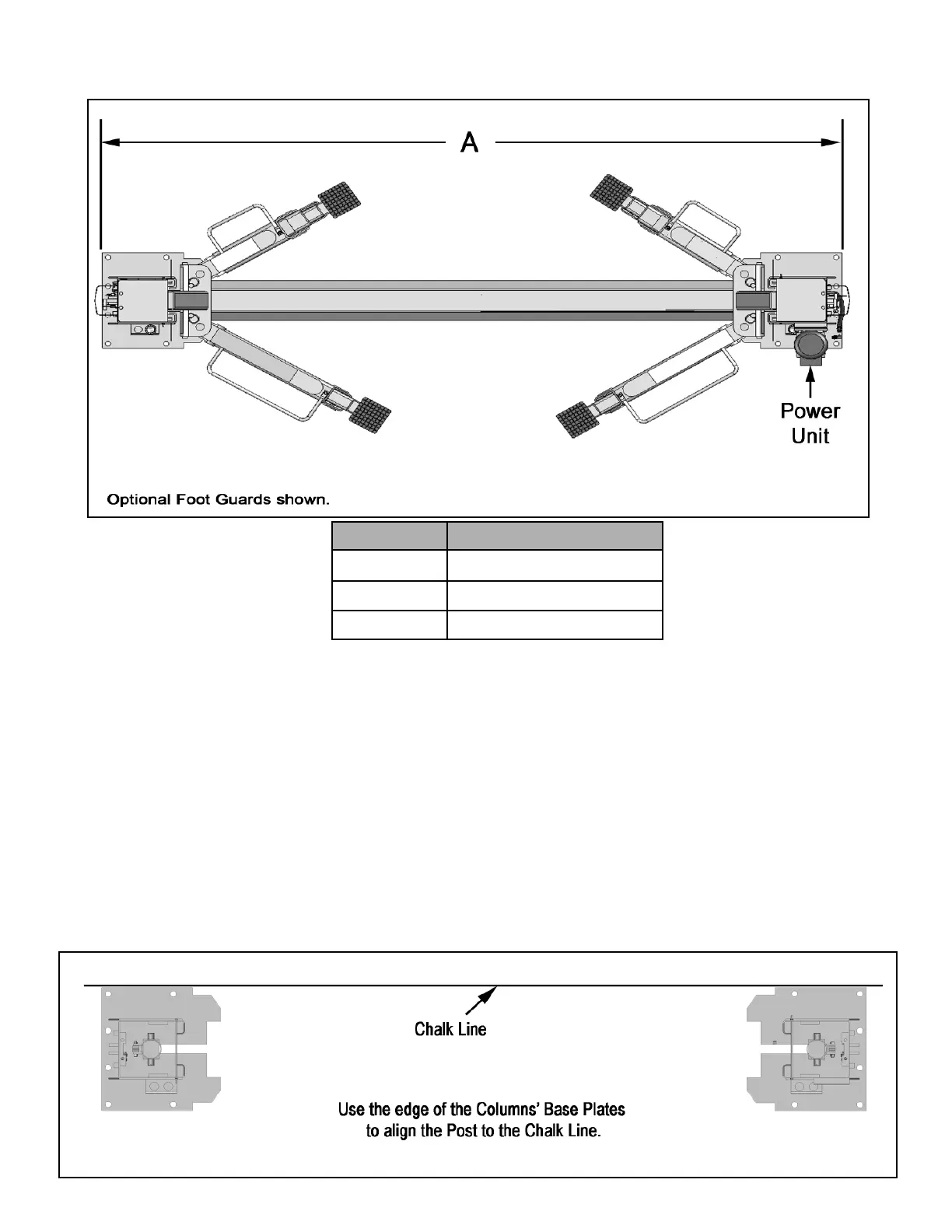
2. Now determine which side you prefer the power unit to be
located on. The POWERSIDE column has the power-unit
mounting bracket attached to the side. ( See diagram above
for power unit location. )
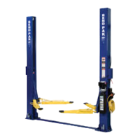
3. Once a location is determined, use a carpenters chalk line
to layout a grid for the Column locations. Keep all
dimensions and squareness within 1/8” or malfunctioning of
the lift will occur.
4. After the Column locations are properly marked, use a
chalk or crayon to make an outline of the Columns on the
floor at each location using the Column baseplates as a
template.
5. Double check all dimensions and make sure that the
layout is perfectly square.
6. Before continuing with the installation it is helpful to stand
the Columns up at their respective locations and get a visual
of the shop, aisles and other clearances. Also, this is a good
time to drive a vehicle into position and check for adequate
clearance.
Floor Plan / Layout
Model A
XPR-9FD 3353mm / 132”
XPR-9XFD 3683mm / 145”
XPR-12FD 3937mm / 155”