31 Bentone
Suction line tables
The suction line tables consist of theoretically calculated
values where the pipe dimensions and oil velocity have
been matched so that turbulences will not occur. Such
turbulences will result in increased pressure losses
and in acoustic noise in the pipe system. In addition to
drawn copper piping a pipe system usually comprises
4 elbows, a non-return valve, a cut-off valve and an
external oil filter.
The sum of these individual resistances is so insignificant
that they can be disregarded. The tables do not include
any lengths exceeding 100 m as experience shows that
longer lengths are not needed.
The tables apply to a standard fuel oil of normal
commercial quality according to current standards. On
commis sioning with an empty tube system the oil pump
should not be run without oil for more than 5 min. (a
condition is that the pump is being lubricated during
operation).
The tables state the total suction line length in metres at
a nozzle capacity of 2,5 kg/h. Max. permissible pressure
at the suction and pressure side is 2,0 bar.
Purging
On 1-pipe systems it is necessary to purge the pump.
On 2-pipe systems purging is automatic through the
return line.
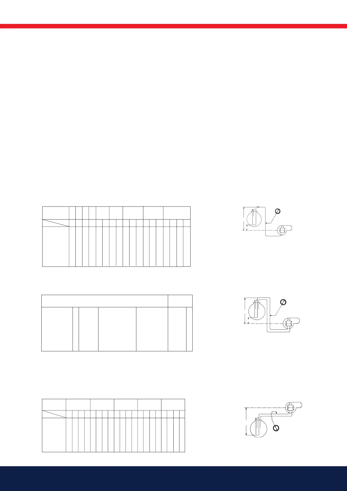
1.1.1 Suction line tables
1.1.1.1 Overlying tank
1-pipe system
0 90 75 56 45
0,5 100 83 63 50
1 110 92 69 55
2 131 109 82 65
3 152 126 95 76
4 172 144 108 86
30 150 22 113 11 56 150 7 37 119 4 23 74 150
33 150 25 126 12 63 150 8 41 133 4 26 83 150
37 150 27 139 13 69 150 8 46 146 5 28 92 150
44 150 33 166 16 82 150 10 55 150 6 34 109 150
50 150 38 192 18 96 150 12 63 150 7 39 127 150
57 150 43 218 21 109 150 14 72 150 8 45 144 150
d (mm)
Nozzle*/Düse*
Gicleur*/Ugello*
(US GPH)
0,50 0,60 0,80 1,00 1,50 2,00 4,00 6,00 9,50
H (m)
4 4 4 4 4 6 4 6 4 6 8 4684 6 8 10
*A2L pumps : sum up the 2 nozzles / A2L-Pumpen : Summe der zwei Düsen
pompe A2L : somme des 2 gicleurs / Per le pompe A2L aggiungere n.2 ugelli
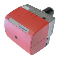
Two-pipe system
0 2 15 50 124
0,5 2 16 56 138
1 2 18 61 150
2 3 22 73 150
3 4 26 85 150
4 4 30 97 150
11 38 96 150 7 27 71 150 20 54 116 150 16 46 100 150
12 42 107 150 8 31 79 150 23 61 130 150 19 52 112 150
13 47 118 150 9 34 88 150 26 68 144 150 21 57 124 150
16 56 141 150 11 41 105 150 31 81 150 150 26 69 148 150
19 66 150 150 13 48 122 150 36 94 150 150 31 81 150 150
22 75 150 150 16 55 139 150 42 108 150 150 35 92 150 150
d (mm)
35/45 55 65 75 95
60 77 102 130 150
Pump/Pumpe
Pompe/Pompa
Q** (l/h)
4 6 8 10 6 8 10 12 6 8 10 12 8 10 12 14 8 10 12 14
H (m)
**Q = pump capacity @ 0 bar / Pumpenleistung bei 0 bar
capacité de l'engrenage à 0 bar/portata della pompa a 0 bar.
One pipe siphon feed system
Einstranginstallation - Tank höher als Pumpe
Installation monotube en charge
Impianti monotubo a sifone
E
d
E max. = 20 m
(E-H) max. = 4,5 m
H
Two pipe siphon feed system
Zweistranginstallation - Tank höher als Pumpe
Installation bitube en charge
Impianti bitubo a sifone
D
H
D max. = 20 m
(D-H) max. = 4,5 m
d
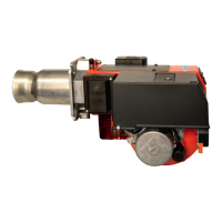
1.1.1.1 Underlying tank
1-pipe system
With an underlying tank a 1-pipe-system is not recommended
Two-pipe system
0 15 50 124 150
0,5 13 44 109 150
1 11 38 95 150
2 7 26 66 138
3 3 14 37 79
84 19
11 38 96 150 7 27 71 150 20 54 116 150 16 46 100 150
9 33 84 150 6 24 62 132 17 48 103 150 14 40 88 150
8 29 73 150 4 20 54 115 15 41 89 150 12 34 76 144
5 19 51 107 2 13 37 80 9 28 61 116 7 23 52 100
10 28 60 6 20 44 4 14 33 65 11 28 55
5 14 9 6 14 4 11
d (mm)
35/45 55 65 75 95
60 77 102 130 150
Pump/Pumpe
Pompe/Pompa
Q** (l/h)
6 8 10 12 6 8 10 12 6 8 10 12 8 10 12 14 8 10 12 14
H (m)
Two pipe lift system
Zweistranginstallation - Tank tiefer als Pumpe
Installation bitube en aspiration
Impianti bitubo in aspirazione
H
H max. = 4,5 m
d