11
Improper installation of the electrical
wiring might cause damage to the snowblower
components.
When assembling the snowblower there are four
elements to connect: the electromagnetic clutch, the
engine’s kill switch, the control of the engine’s electric
starter and connect the engine power supply.
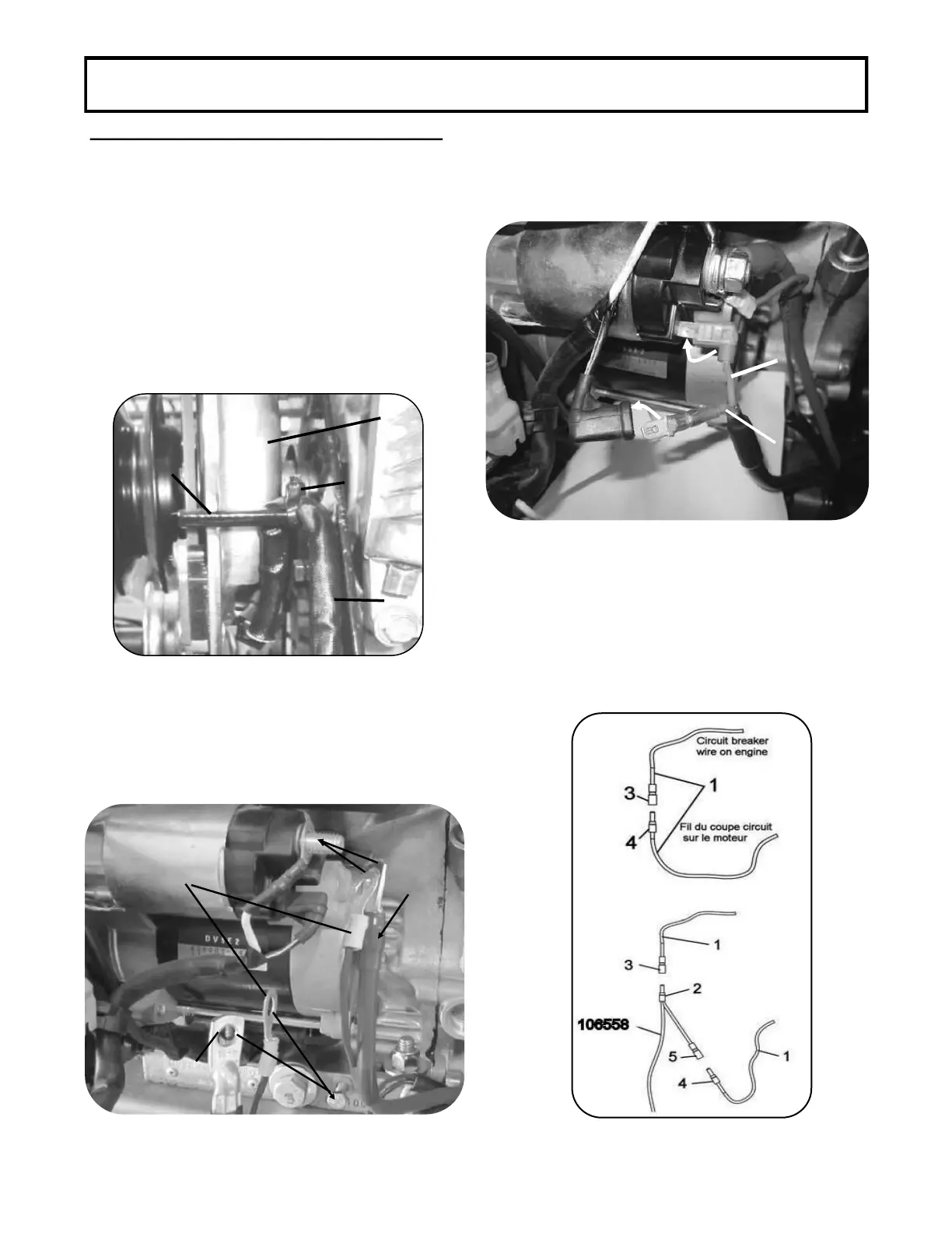
1. Find wire 106548 Pass wire around arm
blocking rotation of clutch and connect it
to the electromagnetic clutch Secure wire
in place with a nylon tie wrap . Shorten tie
wrap to make sure the wire never comes into
contact with the pulleys or belt.
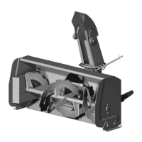
2. Locate connectors of wiring 104018 and 106558.
Connect red wires to the engine’s starter
(solenoid) and the black wires to the base of the
motor as shown.
4. Locate the wire of oil sensor on the engine
and disconnect it. Connect the control box wire
connector to the engine wire
connector . Connect the control box wire
connector to the engine wire
.
The kill switch must be pulled up to start the
snowblower engine.
3. Locate orange and green wiring of the 106558 and
cable going to engine starter and solenoid. Con-
nect as illustrated.
This step is essential since it will pre-
vent the snowblower from being accidentally started.
106558
104018
104018
Red/Rouge
Black/Noir