15
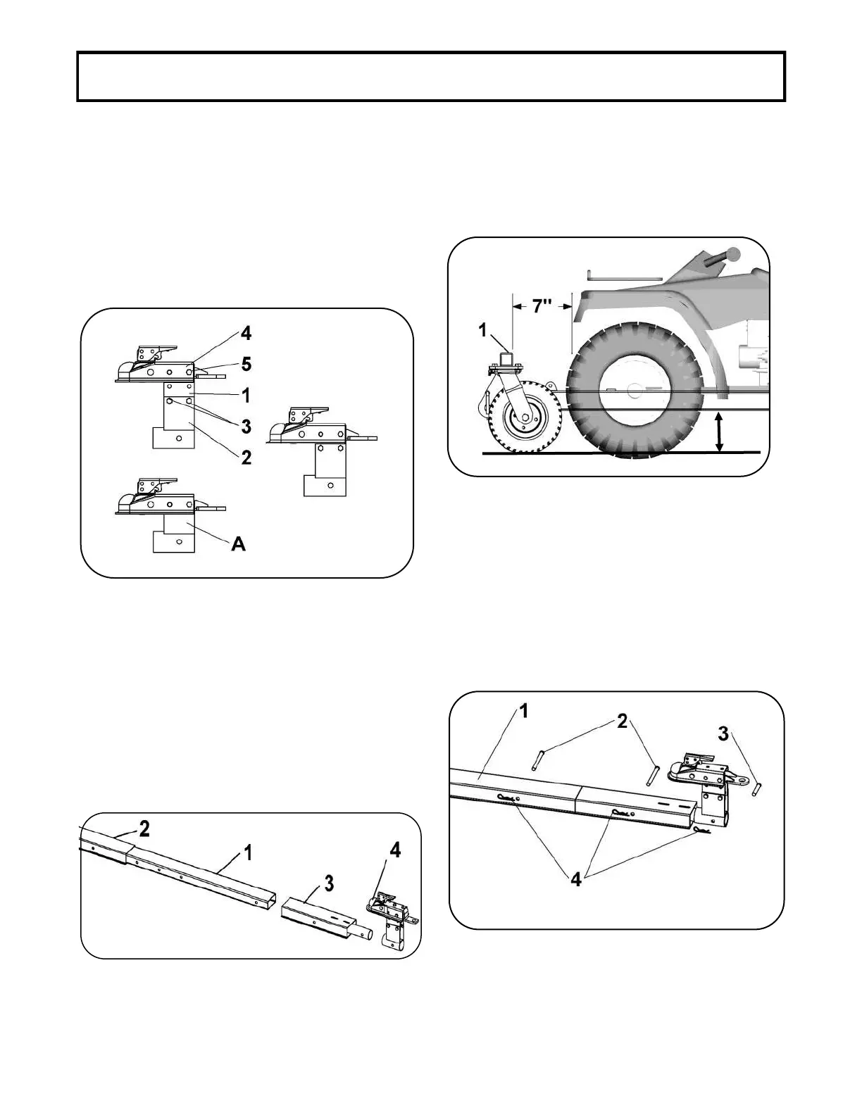
3. Among the three following configurations, choose
the height of the hitch support. There must be a
maximum of ground clearance. (Configuration A)
does not have the hitch support plates
If applicable, assemble the hitch support plates on
the hitch support with four hex bolts 3/8" x
3/4" and four nylon insert lock nuts 3/8".
Secure the hitch on the two hitch support
plates or on the hitch support with a hex bolt 3/8" x
3" and one nylon insert lock nut 3/8".
Tighten firmly
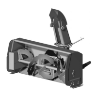
4. There are seven different positions on the
adjustment tube (the adjustment tube can
be inverted) to adjust the length of the subframe. To
choose the right adjustment, insert the adjustment
tube into the subframe and insert the rear
bracket on the adjustment tube. Slide the
hitch support on the rear bracket. Do not
secure.
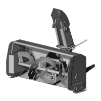
5. Drive the vehicle over the subframe,
Place the hitch under the tow hitch ball and make
sure there is at least 7" (180 mm) between tube on
the wheel support and the most advance
part of the front of the vehicle. Furthermore, the
wheels of the subframe must not touch the front
wheels of the vehicle.
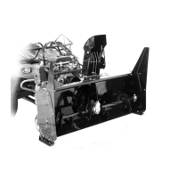
6. Identify the right length of the subframe
and secure in place with two long pins , a
short pin and three hair pins 3mm
~0°
The subframe should be parallel to the
ground as much as possible to allow the casters to swivel
freely.