Function REF: Speed reference selection
TAB2
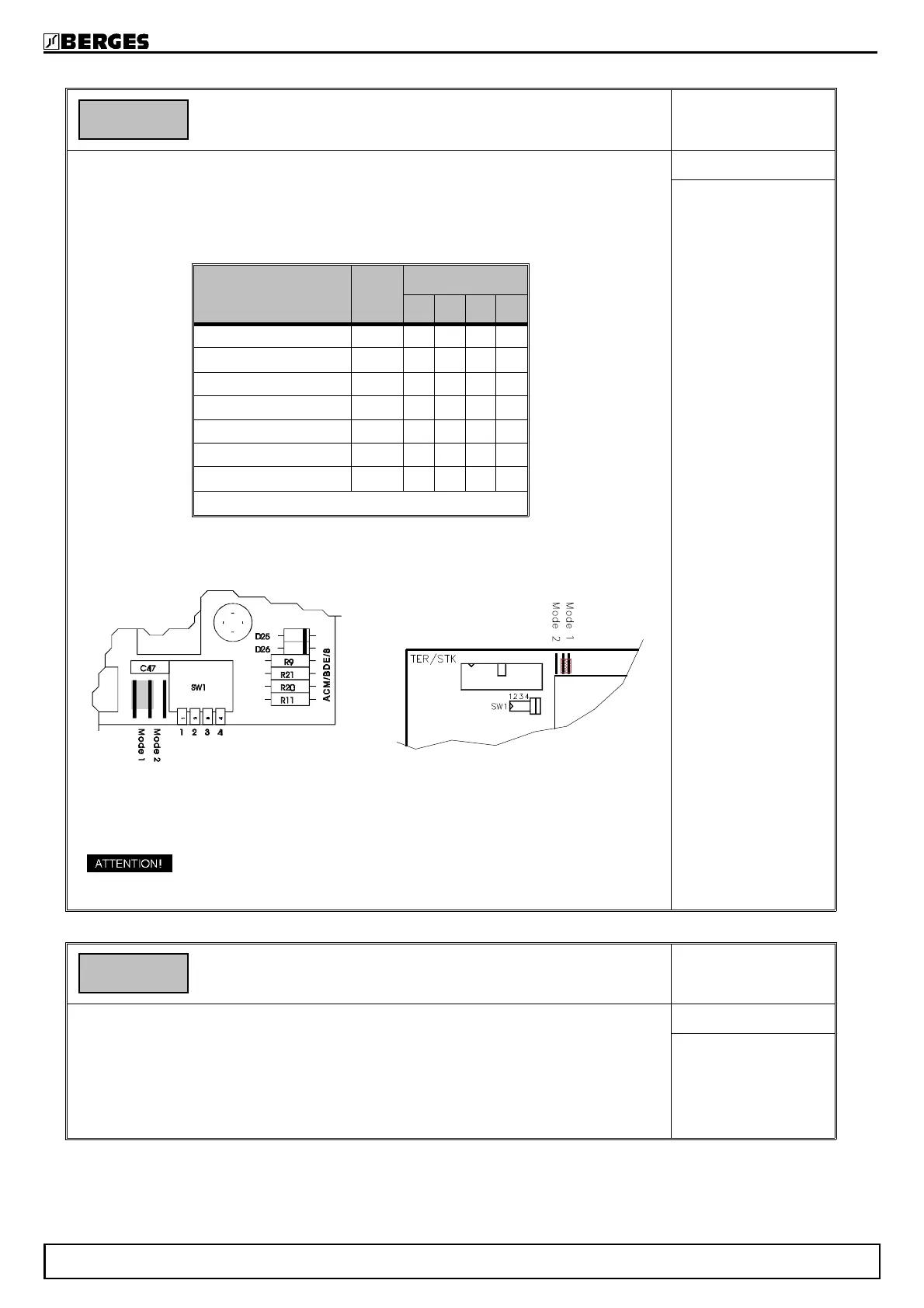
This parameter is used to define the type of external speed reference signal the inver-
ter will be receiving from the corresponding control inputs. In order to work properly the
jumpers must be set corresponding to the selected speed reference type.
Any modification of this parameter becomes active after a save and a restart of the in-
verter (Soft-Reset or POWER ON - Reset). A point in the display indicates that the pa-
rameter value was modified but not saved.
ACM-D2 0.37 - 22.0kW ACM-D2 30.0 - 37.0kW
Control board Control board
* SWITCH SW1-3 and SW1-4 must not be closed if the speed reference input works
as a differential input.
The SWITCH must be set corresponding to the selected
speed reference type.
SUB REF
Range: 1...5
Default: 1
Function Fk: Speed reference scaling
TAB2
Scaling of the speed reference signal is possible by means of the parameter Fk. The
programmed end values of the output frequency range are reached at the percentage
of the scale end values of the selected setpoint range entered in the function Fk.
e.g. selected setpoint range: 4...20mA.
Fk = 50%; Fmax is reached at 10mA and Fmin at 2mA.
SUB REF
Range: 40...100%
Default: 100%
REF 1
Speed reference
type
Value
SWITCH SW1
1 2 3 * 4 *
0...10V 1 o • • o
−10V...0...+10V
2 o • • o
0...20mA 3 o o • •
4...20mA 4 o o • •
10V...0V 5 o • • o
Potentiometer 0...10V 1 o • • o
Potentiometer ±10V
2 • o • o
o = open • = closed
Fk 100%
BERGES electronic
29.05.98 Operating manual ACM-D2 41