18
8. Turn the screw marked “20 mA” so that it reads 20 mA on
the milliammeter.
9. Come back to the closed position and check that for the 0%
position, the signal current shows a value close to 0/4 mA
and repeatable.
5.6 Calibration of positioner (OPTION)
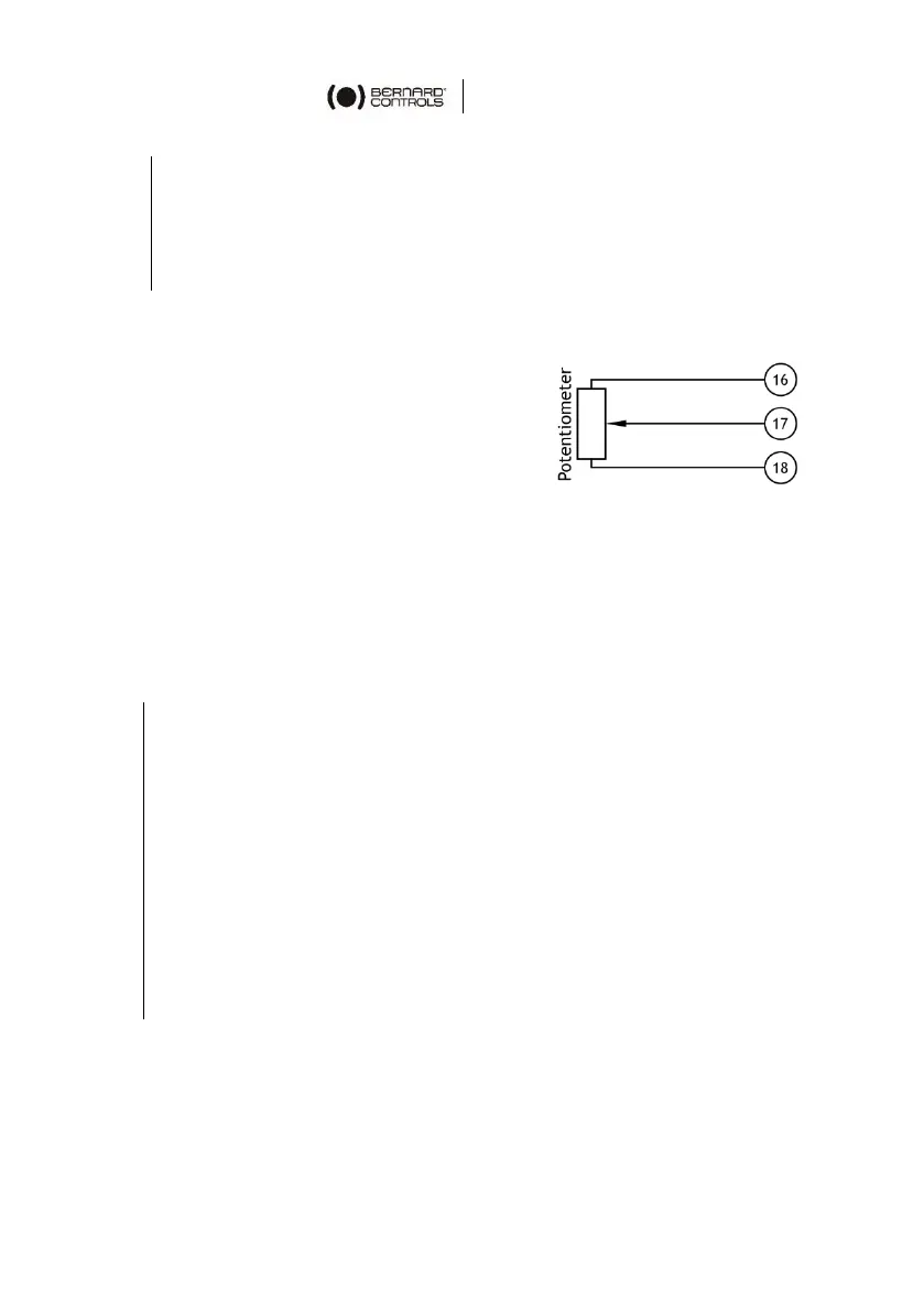
The potentiometer used for actuator
signal feedback is driven by the position
indicator rod.
For clockwise closing:
• The 0% position indicates a closed
valve.
• The 100% position indicates an open valve.
The resistance value is measured between terminals 16 and 17.
How to calibrate potentiometer
You can calibrate the zero of the potentiometer with the 0% position
screw. Use a flat blade screwdriver to turn this screw.
1. Drive the actuator to the CLOSED position.
2. Hold the pinion located just under the plate marked with the
0% position while turning the potentiometer screw.
3. Adjust the potentiometer so that the resistance value exceeds
0 Ohm and regularly increases, then turn backwards to reach
the closest value to 0 Ohm.
4. Drive the actuator to the OPEN position and write down the
resistance value corresponding to the 100% position.
5. Come back to the CLOSED position and check that the
resistance shows a repeatable near zero value for the 0%
position.
Signal inversion
To change the signal variation direction, invert the potentiometer
wires on the terminal block (e.g. for a connection on 16/17/18,
invert 16 and 18).