EasyManuals Logo
Home>Bernard Controls>Controller>AT SWITCH RANGE

Bernard Controls AT SWITCH RANGE User Manual

Bernard Controls AT SWITCH RANGE
24 pages
To Next Page IconTo Next Page
To Previous Page IconTo Previous Page
Page #9 background imageLoading...
Page #9 background image
English
9
5.2 Wiring
Components (with cover open)
9 Cable entry plugs
8 Heating resistance
7 External ground
terminal
6 Internal ground
terminal
5 Terminal blocks
4 Torque limiter
3 Capacitor (only for
single phase actuators)
2 Modular reduction
gear
1 - End position cams
The actuator and its components are wired to internal terminal
blocks.
Installing cable glands
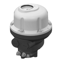
AT SWITCH actuators are fitted with M20 cable glands.
How to install cable glands
For each cable entry used
1. Remove the plug from the cable entry with a 23 mm (M20
entry) open-end wrench.
2. Separate the sealing nut from its cable gland.
3. Screw and tighten the cable gland in the cable entry.
4. Thread the sealing nut on the cable and pass the cable
through the cable gland.
5. When the wiring is finished, tighten the sealing nut on the
cable gland.
Unused entries must be kept closed by their plug.
3
1
2
4
5
6
7
8
9

Questions and Answers:

Question and Answer IconNeed help?

Do you have a question about the Bernard Controls AT SWITCH RANGE and is the answer not in the manual?

Bernard Controls AT SWITCH RANGE Specifications

General IconGeneral
BrandBernard Controls
ModelAT SWITCH RANGE
CategoryController
LanguageEnglish

Related product manuals