11
5.3 Calibration of travel limits
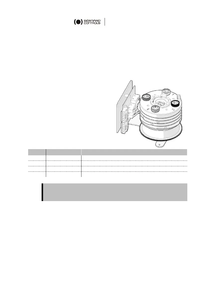
Cam-block detail
To stop the movement at end positions, the AT SWITCH actuator
features a set of cams integrated as a cam block. Cams trip switches
to switch off the power at end positions, or for signaling.
The cam block is made up of 4 cams.
Each one has a specific function and
trips a specific switch.
Each cam can be calibrated thanks
to a screwdriver imprint on the top
of the cam block. The
correspondence between a cam and
its screwdriver imprint can be
determined thanks to numbers and
colors (see figure opposite).
Except for specific valve configurations:
• Clockwise direction generally matches closing direction.
• Counterclockwise generally matches opening direction.