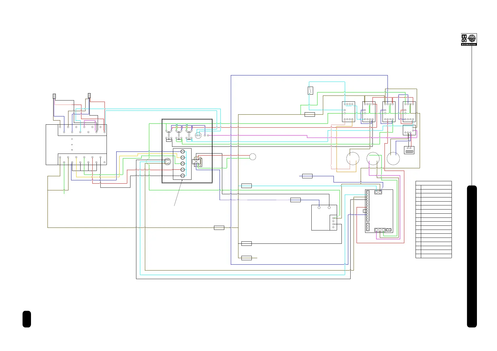
CONTROL
BOX
TRANSFORMER
&
RECTIFIER
INVERTER
1
2
3
4
5
6
7
8
9
10
11
12
13
14
15
L
N
U2
V2
W2
M1 M2 M3
C1 C2 C3 C4
HOUR
METER
N
L
L
E
MAINS
SUPPLY
SUPPLY
MAINS
Fuse #1
Fuse #3
Fuse #7
Fuse #6
Fuse #4
Fuse #2
Microswitch
KEY
M1
M2
M3
C1
C2
C3
C4
Traverse Motor
Reel Drive Motor
Main Motor
Traverse Contactor
Reversing Contactor
Reel Drive Contactor
Main Motor Contactor
O1
O1
Overload
+ -
LINK
P1
SOCKET No.4
Fuse #5
L1
L2
L3
L4
L5
P1 Potentiometer
L1
L2
L.H. Red LED Light
L.H. Amber LED Light
L3
Green LED Light
L4 R.H. Amber LED Light
L5 R.H. Red LED Light
EARTH (GROUND)
NOTE:
Wiring colours shown are
for ease of wire tracing only
and not actual wiring colours,
except for the wires from the
encoders which are shown as
actual colours and also written.
S1S2S3
R1
S1 Grinding Stone Button
S2 Reel Drive Button
S3 Traverse Motor Button
R1 LED Reset Button
L.H. SIDE ENCODER
R.H. SIDE ENCODER
IMO G7
BLUE
BROWN
PWR
ERR
RUN
BLACK
BLACK
RED
BLUE
BROWN
RED
220v AC
220v AC
I00
I01
I02
I03 I05
I04
FG
AC 100-240V
Com0 Com1
Com2
Q00
Q01
Q02
Q03
Com3
Com +485 -485
.
24G 24V
.
WHITE
G7M-DR10A
LED LIGHTS MOUNTED ON A PCB
WIRING DIAGRAM with G7 10 I/O PLC