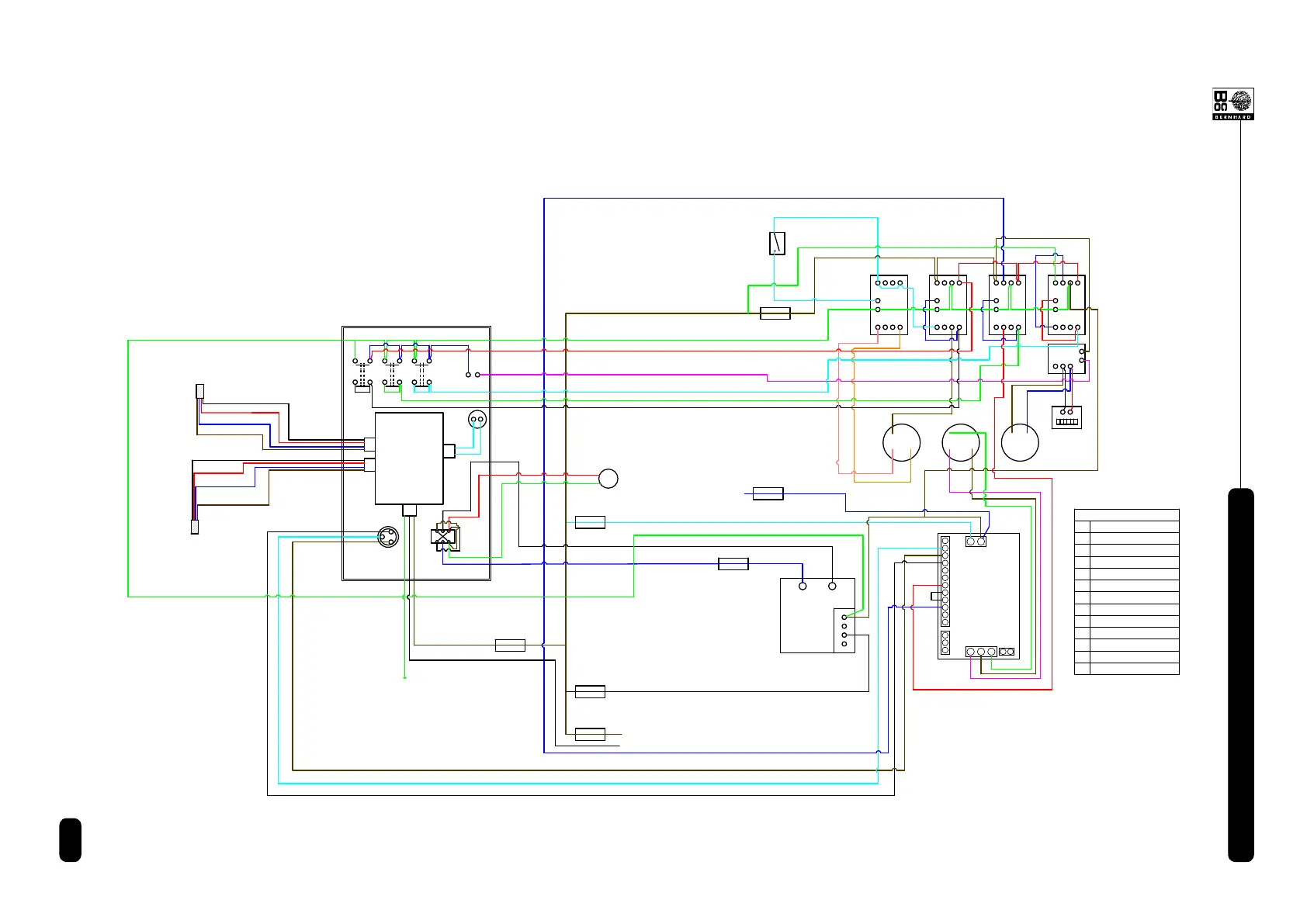
S3
CONTROL
BOX
TRANSFORMER
&
RECTIFIER
INVERTER
1
2
3
4
5
6
7
8
9
10
11
12
13
14
15
L
N
U2
V2
W2
M1 M2 M3
C1 C2 C3 C4
HOUR
METER
N
L
L
E
MAINS
SUPPLY
SUPPLY
MAINS
Fuse #1
Fuse #3
Fuse #7
Fuse #6
Fuse #4
Fuse #2
Microswitch
KEY
M1
M2
M3
C1
C2
C3
C4
Traverse Motor
Reel Drive Motor
Main Motor
Traverse Contactor
Reversing Contactor
Reel Drive Contactor
Main Motor Contactor
O1
O1
Overload
+ -
LINK
P1
SOCKET No.4
Fuse #5
P1 Potentiometer
NOTE:
Wiring colours shown are
for ease of wire tracing only
and not actual wiring colours,
except for the wires from the
encoders which are shown as
actual colours and also written.
S1S2S3
R1
S1 Grinding Stone Button
S2 Reel Drive Button
Traverse Motor Button
R1
L.H. SIDE ENCODER
R.H. SIDE ENCODER
BLUE
BROWN
BLACK
BLACK
RED
BLUE
B
R
O
W
N
RED
P I C
CONTROL
BOARD
L
N
Readout Reset Button
WIRING DIAGRAM with PIC PCB
T1 T2 T3
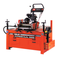
EXPRESS DUAL 3000