Bertec Corporation Instrumented Treadmill Manual 03
System Components
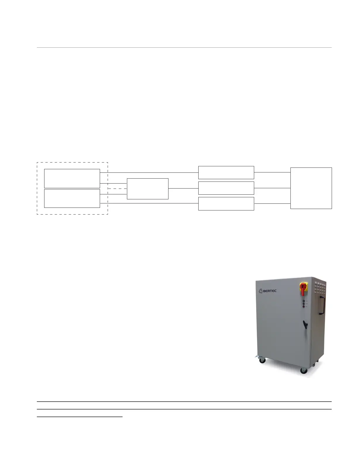
Figure 1 below demonstrates individual components of a typical instrumented treadmill. The split belt treadmill (with optional
incline unit) is connected with 4 cables (6 in case of incline module), each 9 m long, to the Electronic Control Unit. One output
goes to an AM6500-TM unit that is used to control the treadmill via USB port of the computer using a standard USB cable. All of
the FPA cables are standard 10 m long Bertec FPA-10 cables.
All treadmill control is carried out using software on the computer. The Electronic Control Unit does not have any active control
other than an emergency stop button.
* AM6500, AM6501, AM6504, AM6800
** Standard Cable is 1 m long with BNC or Bare Wire output. Should be specied at the time of order.
Electronic Control Unit
The control electronics are housed in a separate cabinet. The cabinet contains an
electronics panel which holds the power electronics, motor drive units, and safety
circuitry. Due to control signal and power restrictions, the maximum distance from the
treadmill motors to the electronics cabinet is roughly 6 m.
Motor power and motor feedback cables exit the bottom of the control cabinet and
can be routed to the treadmill motors either through a conduit or freely on the ground.
These cables should not span any large distances unsupported. The treadmill control
cabinet is connected to a PC running the Bertec Treadmill Control Panel software in the
following manner: A gray cable with a 9-pin d-sub connector exits the control cabinet
and is plugged into an AM6500-TM unit. This AM6500-TM is then connected to the
controlling PC via a USB cable. This PC must be running the Bertec Treadmill Control
Pane software in order to properly control the treadmill belts and/or treadmill incline.
The control cabinet power cord also exits the unit from the bottom.
The electrical network used to supply power to the data acquisition systems and treadmill
electronics rack should be properly grounded. Poor grounding is a common source of signal
noise in electronic systems.
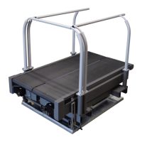
Treadmill Design
Tread 1
Tread 2
Electronic
Control Unit
3-phase power
Computer
AM6500-TM
Signal converter*
Signal converter*
FPA cable
FPA cable
USB cable
Output cable**
Output cable**
FIGURE 1: Instrumented treadmill system layout
Treadmill Electronic Control Unit