Bertec Corporation Instrumented Treadmill Manual 15
Installation Process
The treadmill must be installed by a Bertec approved installation professional. Leave all equipment in boxes before the installer
arrives. Only move with a fork lift or pallet jack if necessary.
During an ideal treadmill installation, the treadmill mounting plate(s) will be glued in the selected location using a two part epoxy.
In the case of an incline treadmill, the incline mechanism is bolted to the mounting plate rst, then the treadmills are attached
to the incline. The treadmills are attached using specially designed large diameter stainless steel nuts. These should not be
loosened by the customer unless under specic instructions from Bertec. In the case of a standard treadmill, each treadmill half
is secured to its mounting plate using the stainless steel nuts mentioned above.
There are several cable connections beyond the inputs and outputs already mentioned
that will be made by the Bertec installer, however a few of these can be disconnected and
reconnected by the end user if needed. The treadmill belt motors are connected to the
control cabinet using one set of (orange) power and (green) signal feedback cables each.
The connections at the control cabinet end will be made by the Bertec installer at locations
inside the cabinet, the cabinet should not be opened by the customer. The connections
at the motor end are simple twist-to-lock connectors that can be released by turning the
connector shell counterclockwise and pulling. They are attached to the motor by pushing
the cable connector all the way on to the motor connector and then turning the shell
clockwise approximately 1/8 of a turn. The treadmill incline motor (if applicable) connects
to the control cabinet in the same manner.
The installer will also connect the treadmill force plates to the ampliers using a gray FPA
cable. This cable plugs into the treadmill at a round port just below the belt motor. The
connection at the amplier is made at the amplier port labeled "Input". The end user can
disconnect and reconnect the ampliers if needed.
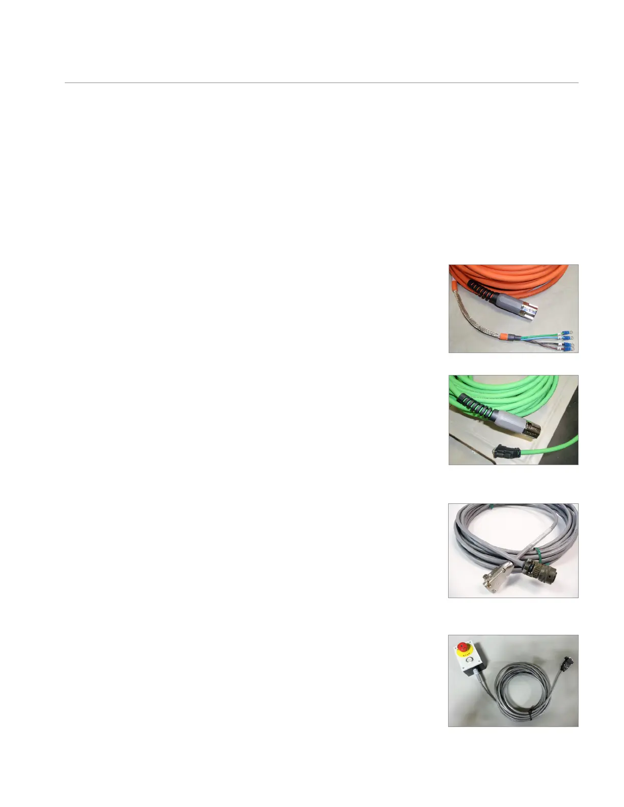
There is one remote E-stop pendant supplied with the treadmill. Its cable will be connected
inside the control cabinet by the Bertec installer and it should not be disconnected by the
end user. Control cabinets with an ITC model number can accommodate up to two E-stop
pendants. A second pendant can be purchased with the treadmill or at a later date.
Orange power cable
Green signal feedback cable
Gray FPA cable
E-stop pendant
Installation