22 Bertec Corporation Instrumented Treadmill Manual
General Amplier Specications
The AM65XX series and AM6800 ampliers provide a ±5 V full-scale calibrated analog output per rated load range for each of
the six force plate channels. For example, if the force plate has a ±10 kN load range for the Fz channel, then for a gain of unity,
the –5.00 V output corresponds to –10 kN, and +5.00 V stands for +10 kN (i.e. a sensitivity of 0.5 mV/N). The analog gain used
in data acquisition represents a trade-off between maximum load range and force plate sensitivity. If the same force plate above
is used with an amplier gain of 5, then the load range will be limited to ±2 kN. This means the plate now has an increased
sensitivity of 2.5 mV/N. The analog load scale factors for specic force plates, given on the product data sheet supplied with the
force plate, are specied for a gain of one.
The analog output signals are ltered so that they have a standard bandwidth of 500 Hz. The actual analog gain ratios are
applied to the digital signal with an accuracy of 99.997%.
The auto zero button removes the signal offset and sets the analog output signal within ±5 mV. This feature can be used to
increase the useful measurement range of the force plate by shifting the signal baseline. Note that auto zero might not set the
mean value of the signal to true zero. Therefore, an additional offset removal through software is suggested.
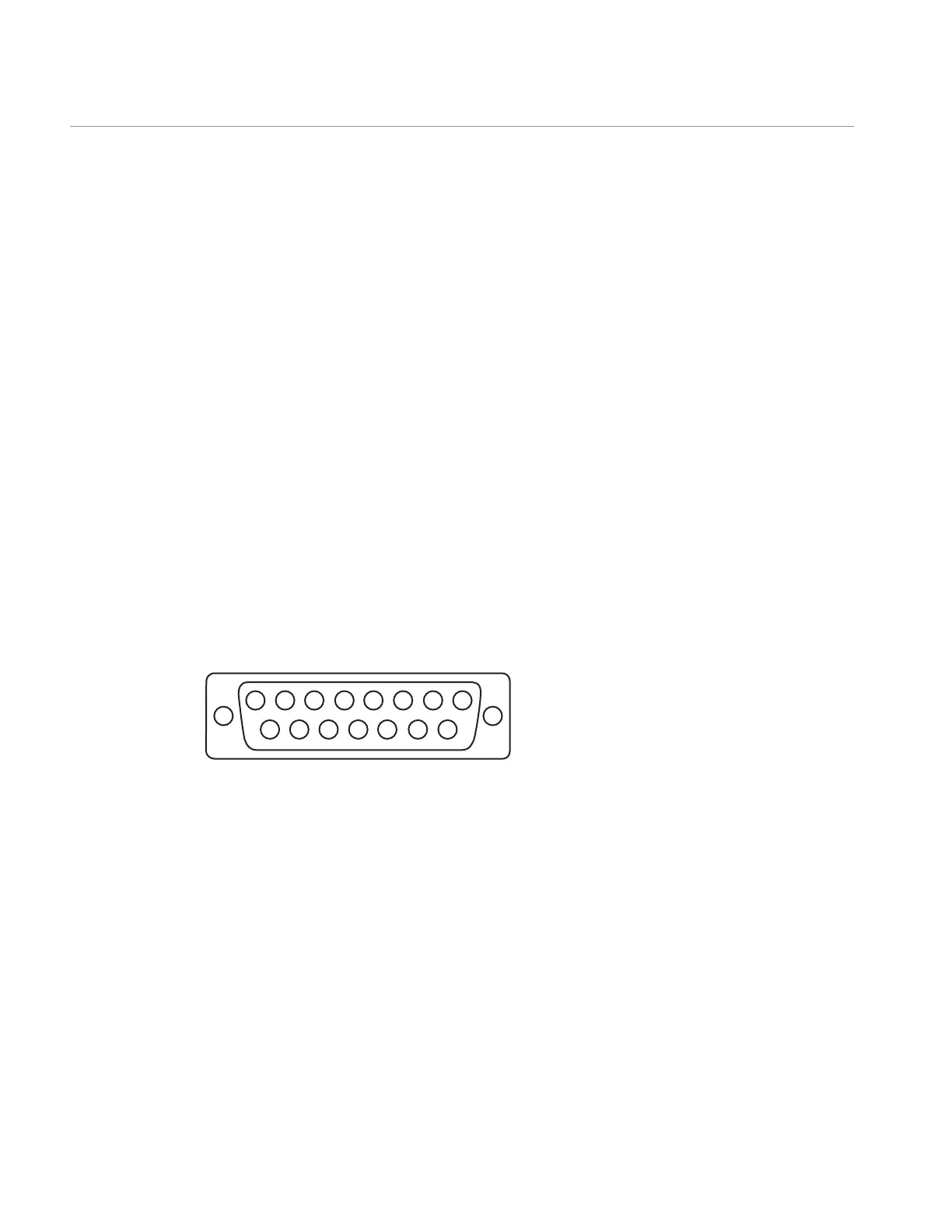
The digital input to all external ampliers and signal converters is a female 9-pin D-Sub connector, whereas the analog output
is in the form of a female 15-pin D-Sub connector with the pin assignments shown below. Shorting pins 9 and 10 has the same
effect as pushing the auto zero button on the AM6501 and AM6800.
The output range for each channel is ±5V.
FIGURE 10: Pin conguration for the standard analog 15-pin connector
Auto Zero
All analog ampliers are equipped with an auto zero button. This button allows zeroing offset loads up to full scale. This
functionality can be used to remove tare weight placed onto the treadmill as part of the measurement protocol. When the
amplier is rst turned on, of the two green lights next to the auto zero button, only the bottom one will be on, conrming that
the amplier is powered. This indicates that zero has not been set yet. Simply press and release the auto zero button in order to
zero the bridges on the amplier. When zero is set, both lights next to the auto zero button will be on.
For the 6800 series ampliers, the auto zero button is next to the power switch on the front panel. For the 65XX series ampliers
it is located next to the 15-pin output connector.
Note that auto zeroing sets all channels to near zero. True zeroing should be done by software at the time of data collection by
subtracting a baseline reading from the collected data.
Data Acquisition and Load Calculations
8 7 6 5
4
3 2 1
9101112131415
CH1 : Pin 3
CH2 : Pin 4
CH3 : Pin 5
CH4 : Pin 6
CH5 : Pin 7
CH6 : Pin 8
Auto zero: Pin 9
GRND : Pin 10