20 Bertec Corporation Instrumented Treadmill Manual
Signal conditioning and amplication for the treadmill force plates are provided by means of external ampliers. All Bertec
products use a novel 16-bit digital technology using RS-485 format for signal acquisition and conditioning. The output signal
of the load transducers are already digitized and conditioned in the treadmill force plates by using state-of-the-art electronics
developed by Bertec Corporation. With this new technology, the output signal has a very high signal-to-noise ratio, which means
increased sensitivity and accuracy for the force plates. In addition, the digital technology makes the use of calibration matrices
obsolete, since each plate comes with the calibration matrix already digitally stored on it. Depending on the conguration, the
system provides the user with a digital, analog, or dual digital/analog output.
The digital output of the system is always in the form of calibrated data in their respective units selected by the user (N and N•m,
or lb and lb•in). External digital-to-analog (D/A) converters are used in order to obtain an analog output to be used in conventional
data acquisition systems. The D/A converters are also analog ampliers with either a unity (6501 series) or adjustable gain (6504
and 6800 series) setting.
Before starting to collect data, make sure that all of the cables from the treadmill to the control electronics, from the control
electronics to the ampliers, and from the ampliers to the computer are properly connected. The force plates reach thermal
stability in about 5 minutes. Therefore, always allow the equipment to warm up at least for 5 minutes before collecting data.
Ampliers and Signal Converters
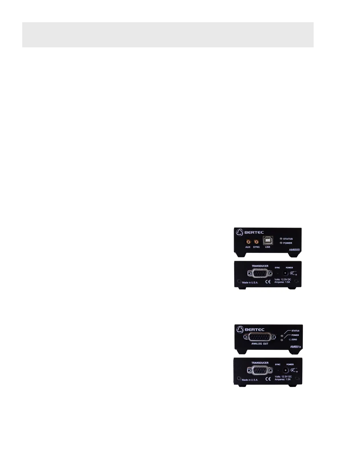
AM6500 Digital Signal Converter
The AM6500 series external converter is used to control the motion of the treadmill
belts. It can also be used to collect data through the USB port of the computer. The
input-output connections for the AM6500 module are shown in the gure below. The
output is a standard B-type USB connector. Next to the connector are two LED lights.
The lower light is on when the unit is powered, and the upper light comes on if the unit
is connected to the USB port of the computer. The input to the module is via a 9-pin
D-Sub connector located at the back of the unit located next to the power input. When
they are used with treadmills, no external power source is needed.
AM6501/AM6504 Analog Amplier
The AM65XX series external analog ampliers are utilized to convert the digital output
of the treadmill force plates to an analog signal using a xed or variable gain value.
The number of gain values is indicated by the sufx XX in the model identier (i.e.
6501 – unity gain, 6504 – gain of four, etc.). These ampliers also provide an auto
zero button to remove tare load offset. When they are used with treadmills no external
power source is needed.
The input and output connections to the AM65XX modules are shown in the gure
to the right. The pin assignments for the analog output channels are shown in the
General Amplier Specications section. The output voltage range for all channels is
±5V. Shorting pins 9 and 10 on the 15-pin output connector has the same effect as
pushing the auto zero button.
Data Acquisition and Load Calculations
AM6500 Digital Signal Converter
connections
AM65XX series connectors