24 Bertec Corporation Instrumented Treadmill Manual
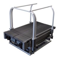
FIGURE 11: Coordinate system for load measurements, right half of treadmill
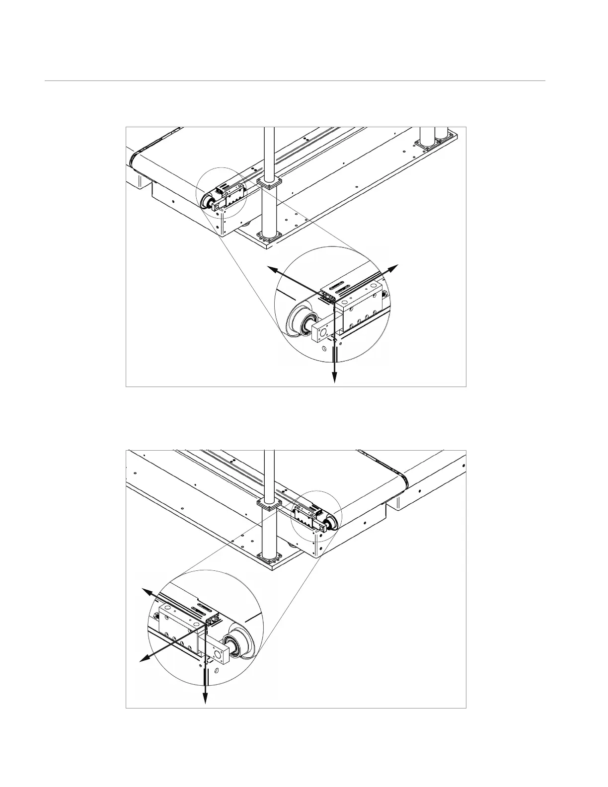
FIGURE 12: Coordinate system for load measurements, left half of treadmill
Data Acquisition and Load Calculations
The center of the coordinate system is at the inner corner of the arm block with the y-axis
forward, x-axis to the left (pointing inwards looking from behind), and z-axis downward.
The center of the coordinate system is at the inner corner of the arm block with the y-axis is
forward, the x-axis is to the left (outwards, looking from behind), and the z-axis is downward.
x
y
z
x
y
z