Transport, Installation and Connection
4-5
1
3
4
2
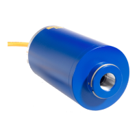
The sight tube connection has a G1" internal pipe thread.
In order to ensure perfect flame monitoring, the correct
and low-vibration position of the sight tube relative to the
flame is a significant pre-requisite. For selective burner
monitoring, the device has to be installed in such a way
that the primary combustion zone in all load ranges is in-
side the visual angle of the compact flame controller. The
view axis should, if possible, intersect the first third of the
flame of the monitored burner. The extension of the view
axis must not intersect the first third of the flame of other
burners. Adjust the compact flame controller so that an
optimum view is obtained.
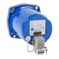
Open housing only by ex-qualified safety personnel!
1 Optical alignment device
2 Compact flame controller
3 Heating insulator
4 Swivel mount
 Loading...