CITY MANUAL INSTALLATION
Versie: 5.0 (04-06-2012) 15
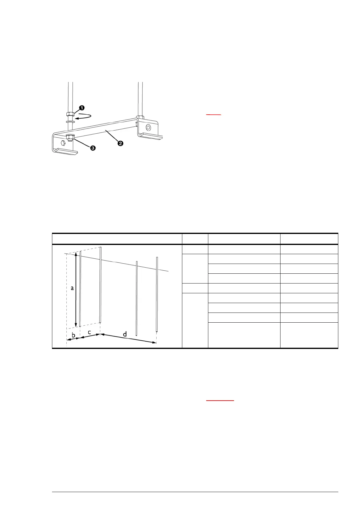
2.4.2 Fixing the suspension brackets
1. Fix four threaded rods M8 according to the dimensions in
the table. Make sure the threaded rods are perpendicular.
Note:
n Units of type CITY 250 have three suspension
brackets. Fix six threaded rods for that type.
2. Apply a lock nut 1 to each threaded rod.
3. Apply the suspension brackets 2 onto the threaded rods,
and a
pply the nuts 3.
4. Make sure the suspension brackets are suspended horizon-
tally and flush.
5. Secure each suspension bracket by tightening the lock
nu
t 1.
Dimensions for suspending unit
2.4.3 Suspending and securing the unit
1. Lift the unit up and hook it into the suspension brackets.
Caution:
c Depending on the weight specified on the type plate,
either use a lifting device or lift the unit with at least
2 persons.
SIZE TYPE DIMENSIONS
a all models as needed
b CITY S 119 mm
CITY M 119 mm
CITY L 200 mm
c all models 200 mm
d CITY 100 500 mm
CITY 150 1000 mm
CITY 200 1500 mm
CITY 250 (six threaded
rods)
2 x 1000 mm
 Loading...