122832 4-3 REV A
To adjust the stops for driving straight when steering
control levers are against the stops during operation:
Before considering any adjustment, check the tire air pres-
sure. Unequal tire pressure will cause the mower to drift to
one side. Refer to tire pressure information in the Tires sec-
tion for detailed information.
1. Remove the front cover.
2. Push forward on the steering control lever until it con-
tacts the steering control lever stop. Repeat for other
side.
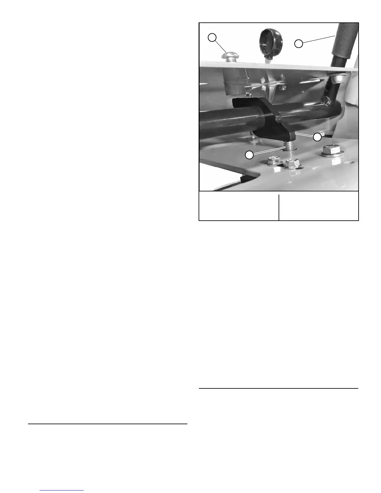
3. Loosen the lock nut and back the speed adjusting
screw out until it does not contact the steering handle
stop. Repeat for other side. Figure 4-5
4. To determine which of the drive wheels is turning the
slowest it will be necessary to drive the machine.
• Test drive the mower on a smooth level surface.
• Start the engine.
• Release the park brake.
• Set the throttle to the full open position.
• Slowly push the steering control levers to the full
forward position.
• Determine which drive wheel is rotating faster.
• Pull the steering control levers to the neutral
position.
• Set the throttle to the slow position.
• Turn engine off.
5. Move the steering control lever on the slower speed
side forward until it makes contact with the steering
control lever stop. Turn the speed adjusting screw
down until it makes contact with the steering handle
stop (finger tight). Tighten lock nut. Figure 4-5
6. Move the steering control lever on the faster speed
side forward until it makes contact with the steering
control lever stop. Turn the speed adjusting screw
down until it makes contact with the steering handle
stop (finger tight). Using a wrench turn the adjusting
screw an additional 1/4 turn. Tighten lock nut.
Figure 4-5
7. Test drive the mower to determine if the wheels are
rotating at the same speed. If not, repeat this proce-
dure until unit drives straight.
NOTE: Since this is a hydrostatic drive, variables such as
temperature of oil, efficiency of pumps and motors, tire pres-
sure etc. may effect the consistency of the ability to rely on
the stops to drive straight without the operator making minor
steering adjustments with the control arms.
Park Brake Adjustment
Before considering any adjustment, check the tire air pres-
sure. Refer to tire pressure information in the Tires section
for detailed information.
1. Release the park brake.
2. Treadlock plate (left side) – Loosen both the carriage
bolts that hold the treadlock plate in place. Figure 4-6
Treadlock plate (right side) – Loosen both the carriage
bolts and adjust the treadlock plate until the carriage
bolts are in the middle of the slots. Tighten the
carriage bolts. Figure 4-7
3. Loosen the hardware that attaches the brake link to
the treadlock mounting bar. Adjust the brake link so
that the gap between the tire and the right treadlock
plate is .75". Tighten the hardware. Figure 4-7
4. Adjust the left treadlock plate so that the gap between
it and the tire is .75". Figure 4-6
5. Engage park brake lever. The park brake plate should
push in on the tire to prevent it from rotating.
6. If one of the treadlock plates does not fully engage the
tire then it may be necessary to readjust the treadlock
plate until it fully engages the tire.
Belts
Inspect belts frequently for wear and serviceability.
Replace a belt that shows signs of:
• severe cuts
• tears
• separation
• weather checking
• cracking
• burns caused by slipping.
A. Steering control lever
stop screw
B. Steering control lever
C. Speed adjusting screw
D. Steering handle stop
Figure 4-5