FDL (E2.1) 05/2016 page 15/75
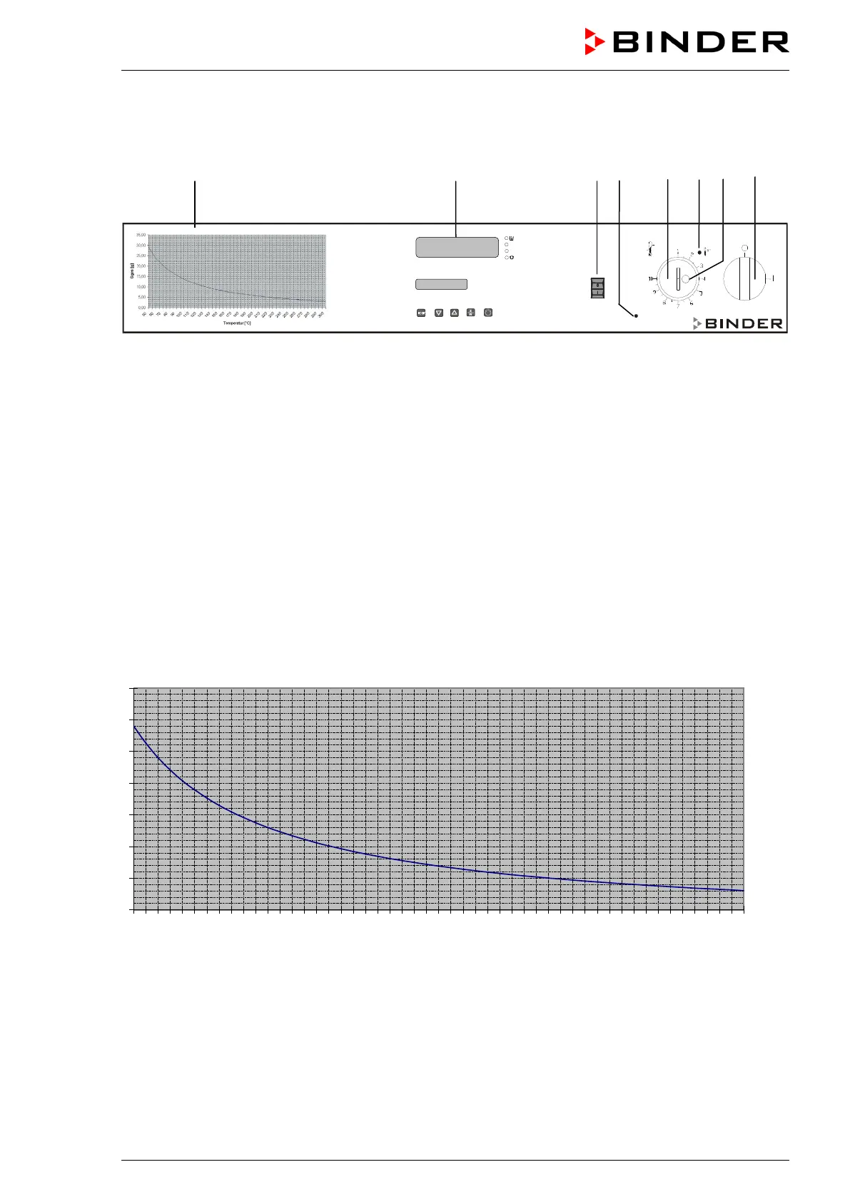
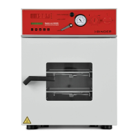
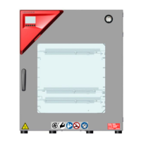
2.2 Control panel
(6) (5) (4) (3)
(2) (2a) (2b) (1)
Figure 4: Control panel of FDL 115 standard chamber
(1) Main power switch ON/OFF
(2) Temperature safety device class 2
(2a) Red pilot lamp for temperature safety device class 2
(2b) RESET key for temperature safety device
(3) Red indicator light “AIR”: Heating turned off during prepurge or due to insufficient exhaust air
stream (loss of technical ventilation)
(4) Pushbutton “START”: starts the fan and the prepurge procedure
(5) Temperature program controller RD3
(6) Solvent curve: Highest permissible amount of solvent G
total [g] as a function of the drying tempera-
ture
2.3 Solvent curve FDL 115
0,00
5,00
10,00
15,00
20,00
25,00
30,00
35,00
Figure 5: Solvent curve FDL 115
The diagram shows the highest permissible solvent quantity G
total [g] in the steam room in correspond-
ence to the drying temperature. This is based on the calculation acc. to EN 1539:2015 considering the
chamber specific data, an assumed molecular weight of the solvent of 100g/Mol, and a lower explosion
limit of 40g/m
3
at 20 °C / 68 °F and at 760 Torr (1013 hPa) (assumptions for unknown solvents acc. to EN
1539:2015).