KMF (E5.2) 06/2014 page 48/99
9.4 Selecting between “set-point ramp” and “set-point step”
Set-points always refer to the start of a program section, i.e., at the beginning of each program section
the entered set-point is targeted. During program section operation, the temperature or humidity gradually
passes to the set-point entered for the next program section.
By appropriate planning of the program section timing, you can enter all kinds of temperature and humidi-
ty transitions:
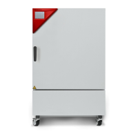
• Gradual temperature / humidity changes “set-point ramp”
The set-point changes its value gradually while proceeding from one program section to the next one
during the programmed section length. The actual temperature or humidity value (X) follows the con-
tinually moving set-point (W) at any time.
• Program sections with constant temperature / humidity
The initial values of two subsequent program sections are identical; so the temperature or humidity
remains constant during the whole time of the first program section.
• Sudden temperature / humidity changes “set-point step”
Steps are temperature or humidity changes (ramps) that occur during a very short interval. A section
with a different set-point follows two program sections with an identical set-point. If the duration of this
transitional program section is very short (minimum entry 1 sec), the temperature or humidity change
will proceed rapidly within the minimum amount of time.
Figure 15: Possible temperature or humidity transitions
The following chapter offers examples of programming a “set-point ramp” and a “set-point step”.
9.5 Program entry as “set-point ramp” or as “set-point step”
In order to avoid incorrect programming, we recommend plotting both the temperature and humidity pro-
files (chart templates in chap. 9.11 and 9.12) and entering the values into a table (templates in chap 9.13
and 9.14).
The controller provides 8 operation lines (non-functional with standard unit) that can be activated or de-
activated for each program section.