Instruction Manual
Page 31 of 40 Issue: 2.1
N:\Engineering\Manuals\Pump Unit E2-30 & 40 R2.1.doc
Maintenance – Section 6.1 - Assembly Procedure
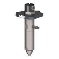
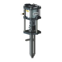
Fluid Section Assembly [2]
1. Place a shaft / bellows assembly (192679) into the pocket on the back of the inlet
cylinder (82). Hold in position and loosely assemble with 4off M6 x 25 long screws
(109) and washers (108) use loctite 222 on the threads.
2. Lightly lubricate with suitable grease a piston seal (81) and push the seal onto
the piston assembly (192678 or 192754) with the seal lip facing away from the
shaft end of the piston.
3. Apply Loctite 243 to piston shaft thread and loosely screw the Piston assembly
onto the piston shaft. Locate the piston seal (81) into the inlet cylinder (82) (this
will centralize the piston). Hold the piston and prevent from turning with 14 mm
Allen key, tighten the piston onto the shaft with 16mm spanner to 55Nm. Finally
tighten 4 off screws (109) to 12Nm.
4. Locate the outlet cylinder (80) over the piston seal until there is a small gap
between the cylinders.
5. Lightly grease the thread of 4off M12x40 caphead screws (90) and assemble with
4off Ø12 washers (93) to hold the cylinders together. Tighten evenly the caphead
screws in a ‘criss cross’ fashion to 50Nm.
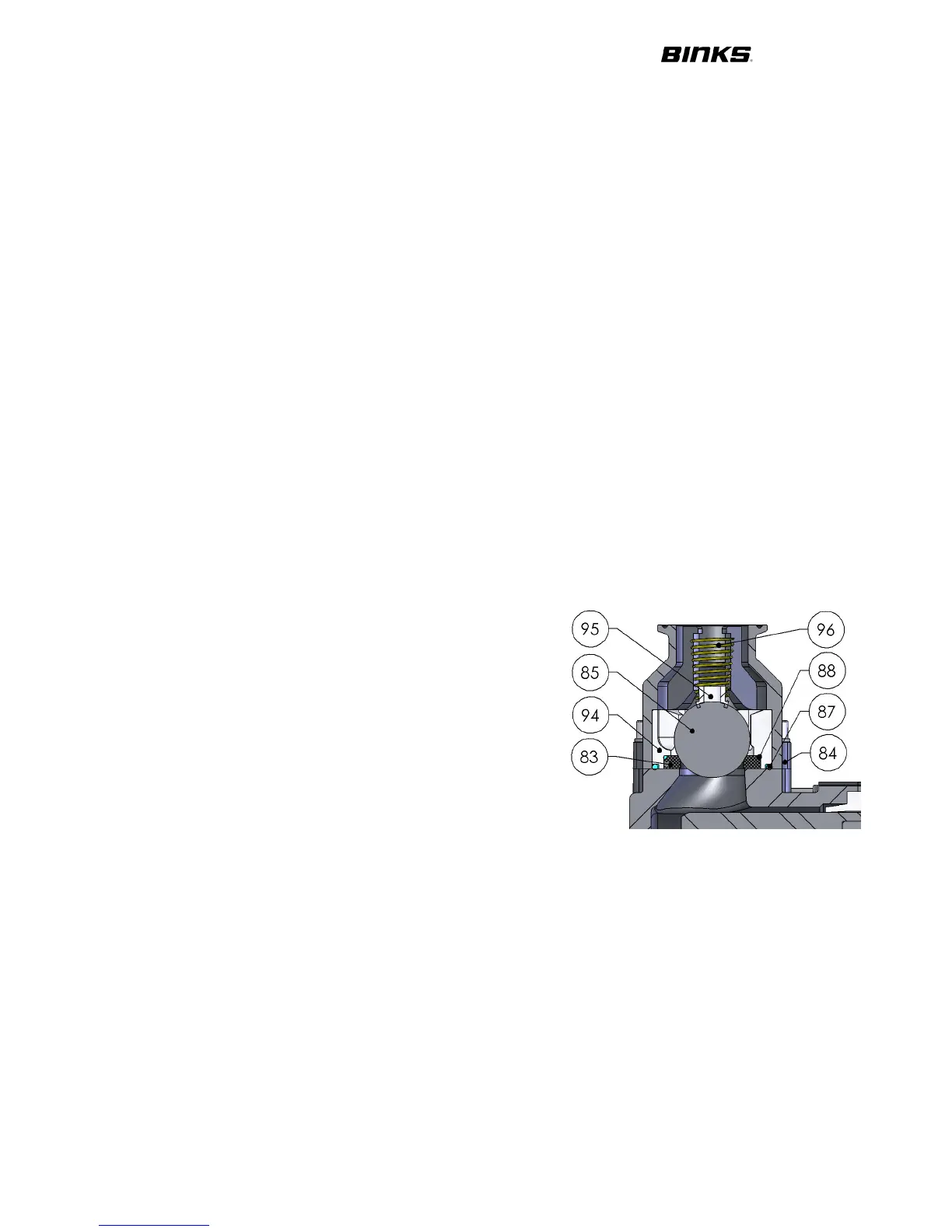
6. Assemble the outlet ball checks:- place spring
(96), spring keep (95) and ball (85) into outlet
check (84)
7. Fit o-ring seal (88) and outlet seat (83) into
outlet cage (94). Fit o-ring seal (87) onto outlet
cage.
8. Fit outlet check and outlet cage assembly
together and position on outlet cylinder (80).
9. Grease threads of 4 off M8x25 caphead screws
(92) and washers (91) and secure. Tighten
evenly to 20Nm.
10. Fit threaded plug (86) with sealing o-ring (89)
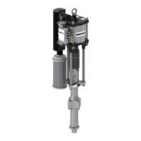
Assemble Fluid Sections to Main Drive Assembly
1. Hold a fluid section assembly [2] and feed the piston shaft through the side of the
mechanical assembly casting, locate the bellows spacer into the counterbore in
the casting. Lightly grease thread of 4off M12x40 caphead screws (128) and 8off
Ø12 washers (127) to hold the cylinders to the side plate. Tighten all caphead
screw to 25Nm in ‘criss cross’ fashion and then to 50Nm
2. Pull the piston shaft until the shaft and the carriage adaptor are touching. Fit the
quick release shaft clamp (48) and tighten to 20Nm