Instruction Manual
Page 32 of 40 Issue: 2.1
N:\Engineering\Manuals\Pump Unit E2-30 & 40 R2.1.doc
Maintenance – Section 6.1 – Assembly Procedure
Final Assembly
1. Use suitable lifting equipment move the pump assembly from the bench to the
floor (Note: Overall weight at this point of the assembly is 180 Kg) Using suitable
rope slings around the legs, turn the pump over to stand on the legs. The pump is
now in the operational orientation.
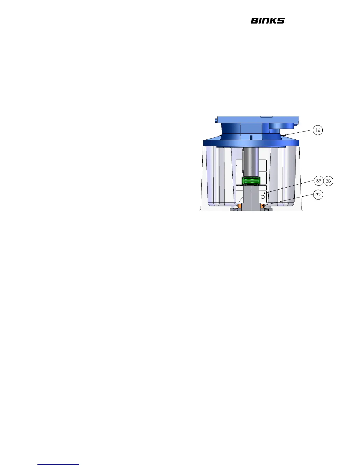
2. Lightly grease and fit the shaft bearing
locknut (32). Hold the main shaft and
tighten nut using special castellated tool
(502508).
3. Insert the 4 off m12 X 50 Grub screws
(16) into the top casting, use loctite on the
threads.
4. To assist with future disassembly, Brush
‘copperlite’ grease or equivalent onto the
inside of the coupling half (39). Place the
key (38) onto the main shaft and then
slide the coupling half over the shaft and
key, until firmly against the shaft shoulder. Apply Loctite 222 to the M8 clamping
cap head screw and tighten to 22Nm. Fit the green spider into the coupling half.
5. Brush ‘copperlite’ grease onto the gearbox shaft and key. Slide the other coupling
half over the gearbox shaft and key until flush with the end of the shaft. (this is
important as it ensures there is no axial preload on the spider and bearing) Apply
loctite 222 and tighten the M8 clamping cap head screw to 22Nm.
6. Using suitable lifting equipment, lower the motor / gearbox assembly onto the
pump assembly, ensure that the spider correctly locates into each coupling half.
Fit the 4 off M12 hexagon nuts (123), plain washers (122), tighten to 40Nm.
7. Fit inlet manifold (129) to the pump with 1 1/2” sanitary clamps (132) and seals
(131) to the orientation required.
8. Fit outlet manifold (130) to the pump with 1 1/2” sanitary clamps (132) and seals
(131) to the orientation required.
9. Fit the 4 off cover spacers (36) over the grub screws (15) and fit ‘O’ ring (37) over
cover spacers.
10. Fit the covers (133) over the cover spacer and secure with M8 Security TORX
screws (134) and nylon washers (135)
11. Screw in the 2 off Lifting eye bolts (35)
12. Finally fit the bellows indication arrangement:- 2 off elbow (46) 2 off hose (47) and
1 off hose plug (45)