Instruction Manual
Page 5 of 40 Issue: 2.1
N:\Engineering\Manuals\Pump Unit E2-30 & 40 R2.1.doc
Operating Principle – Section 1.2
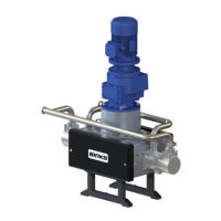
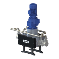
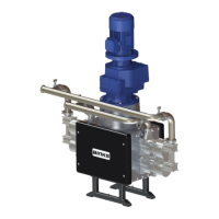
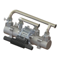
The Assembly comprises of:-
• 1 off Electric Motor
• 1 off In Line Gearbox
• 1 off Drive Shaft / Cam assembly
• 2 off Cam Follower / Carriage assembly
• 2 off Fluid Pistons
• 2 off Fluid Pressure Chambers
• 1 off Fluid Inlet Manifold
• 1 off Fluid Outlet Manifold
• 2 off Support Stand
An AC Induction electric motor drives the fluid section via a mechanical gearbox.
The electric motor speed is controlled by an AC Frequency inverter, which can adjust
the frequency between 20 and 80 Hz, this being the certified range of the electric
motor. The speed adjustment is made by control of the Inverter Frequency Output
through manual operation or from a PLC analogue output. The motor frequency is
directly proportional to the Fluid Output, (see specifications).
The gearbox is directly coupled to a drive shaft onto which a cam is mounted.
As the cam is rotated one of two diametrically opposed fluid displacement pistons is
pushed via a connecting rod and cam follower / carriage assembly producing the
pressure stroke.
At the same time the other fluid piston is pulled by the opposed cam follower /
carriage assembly producing the suction stroke.
Each of the two carriage assemblies are held in place by 4 compression springs in
order to maintain a constant connection between the cam follower bearings and the
cam.
Ball checks control the fluid flow into and out of the pressure chambers during these
operations.