44
WARNING:
This probe with its cable, such as the standard cable, can only be plugged or unplugged on
the channel board when the instrument is powered OFF.
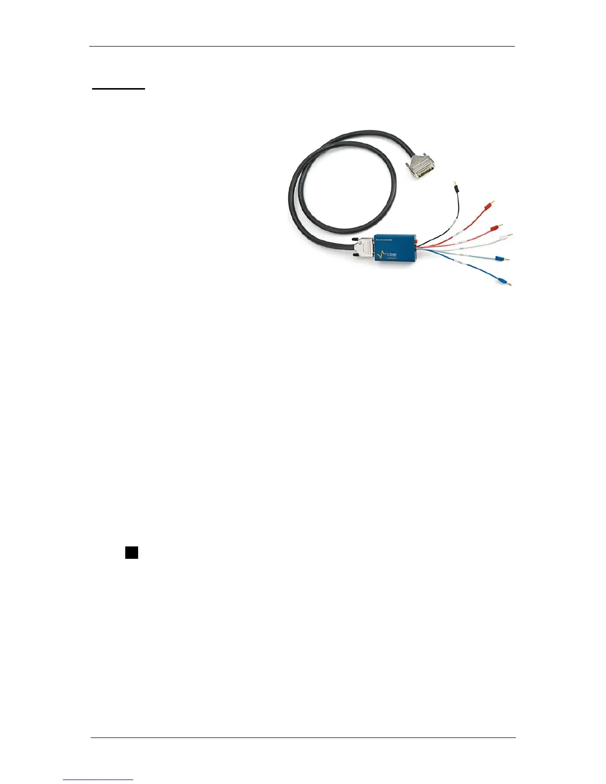
The Ultra-Low Current option is
composed of a cable associated with a
very sensitive low current probe. This
option uses no slot in the instrument
chassis and the low current cable
replaces the standard cable.
This option includes current ranges from
100 nA down to 100 pA with additional
gains extending the current ranges to
10 pA and 1 pA. The resolution on the
lowest range is 76 aA.
This option is compatible with another
option the 1 A/48 V booster providing
then current autoranging from 1 pA to 1 A.
Fig. 58: Ultra Low current cable
This option can be used both with EIS (maximum value 3 MHz) and standard channel boards.
The Ultra-low current option can also be used 2A, 4A and 10A boosters. The lowest Irange is
1µA.
This option can be calibrated using EC-Lab
®
software for DC measurements. For AC
measurements, and in order to keep very good specifications at high frequencies (up to
3 MHz), it is necessary to calibrate the AC part at the factory with its associated channel board.
Both cables offer 6 terminals after the electrometer. Each of this lead is ended with stackable
2 mm bananas for the connection to the electrochemical cell. The ULC electrometer offers also
a Guard connector (red socket of 2 mm) which allows user to protect the cell from external
perturbations.
A channel has 6 leads connections plus the 2 leads coming from the booster board to the
electrochemical cell. Four are used in the cell control loop (2 for the current and 2 for the
potential) while the 5
th
lead permits simultaneous recording of a supplementary cell potential.
Additionally, a 6
th
“ground” lead is provided for cell shielding purposes or particular cell
arrangements. To be easily identified, each lead has an associated color and label as follows:
S1: RED – Sense 1 for the control and measurement of the Working electrode potential.
S2: WHITE – Sense 2 for the control and measurement of the Reference electrode
potential.
S3: BLUE – Sense 3 for the control and measurement of the Counter electrode
potential.
P1: RED – Power 1 for the control and measurement of current flowing through the
Working electrode.
P2: BLUE – Power 2 for the control and measurement of current flowing through the
Counter electrode.
GND: BLACK – Ground
The internal structure of the channel board offers two working modes: grounded and floating.
To switch from one mode to the other, no connection change is required.
A channel has the ability to link up with 2, 3, or 4 electrodes in different configurations
depending on the electrochemical cell. E
we
and E
ce
are measured as follows:
 Loading...