Manual for VMP300-based instruments
47
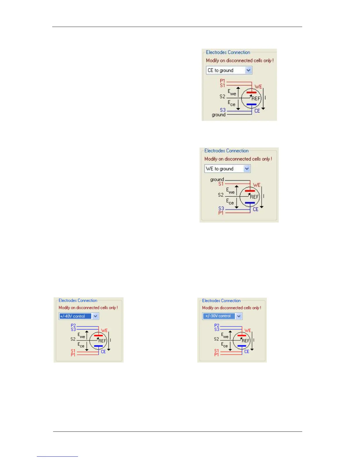
5.2.3 CE to Ground connection mode
This connection mode is chosen in the
software “Advanced settings” window. Then
the connections must be done in a special
way, in connecting the ground cable to the
CE electrode of the cell, as shown below:
Fig. 64: CE to Ground connection mode.
5.2.4 WE to Ground connection mode
This connection mode is chosen in the
software “Advanced settings” window. Then
the connections must be done in a special
way, in connecting the S1 and the Ground
cable to the WE of the cell and S3 and P1 to
the CE electrode of the cell, as shown below:
Fig. 65: CE to Ground connection mode.
5.2.5 High voltage control connection mode
This connection mode is chosen in the software “Advanced settings” window. Then the
connections must be done in a special way, in connecting the S2 and the P3 cable to the WE
of the cell and S1 and P1 to the CE electrode of the cell, S2 is connected to RE. Connection
is shown below:
NOTE: when this mode is selected the impedance techniques are no more available.
Fig. 66: High voltage control connection mode. Left: +/- 48V for the 1A/48V booster.
Right: +/- 30V for the 2A/30V booster.
 Loading...