50
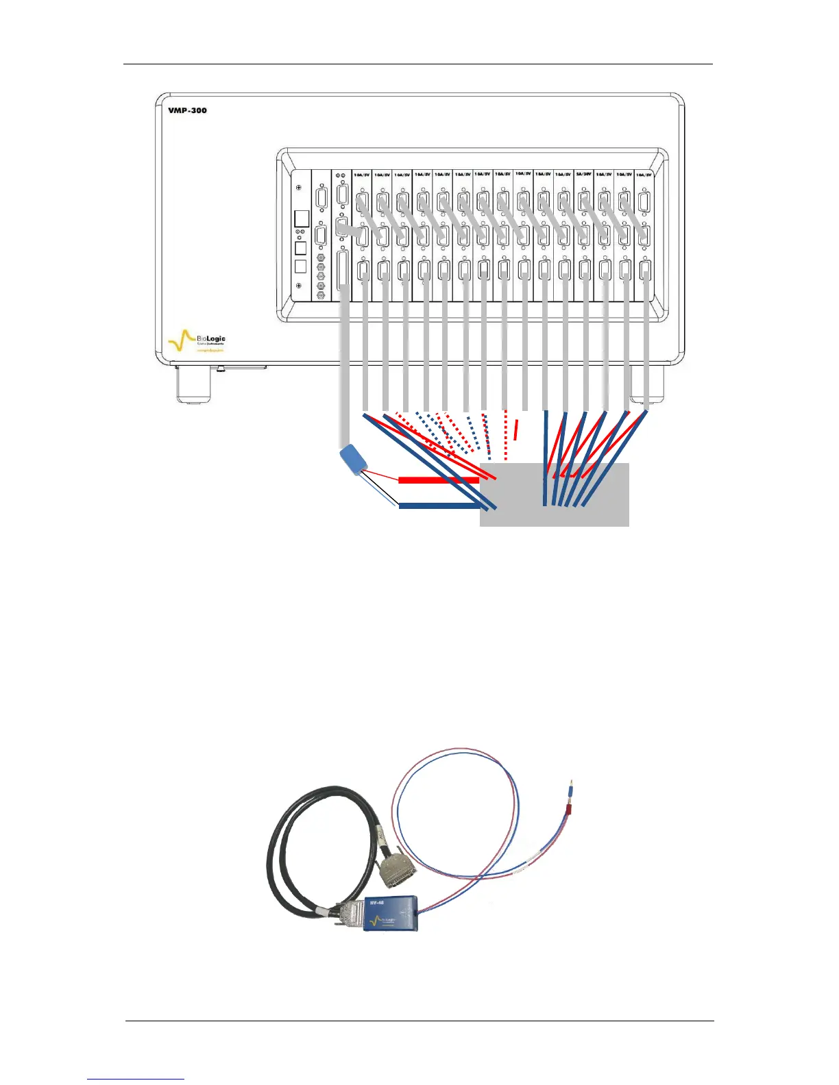
Fig. 70: Channel board connection to the cell with fifteen boosters.
Note: for clarity the P1 and P2 leads coming from the 10A booster cables are not displayed in
the scheme but all the P1 and P2 leads of 10A boosters have to be connected to the cell trough
the current collector.
5.3.3 Connection to the cell with HCV-3048 external booster
5.3.3.1 Standard connection
Two different cell cables have to be used:
.The voltage cell cable also named HV-48 cable connects the pstat/gstat to the cell and
measures the potential. It is only composed of two voltage senses coming from an electrometer
similar to the electrometer of the ULC cable. These voltage senses are protected 4 mm banana
leads.
Fig. 71: Cell cable when used with the HCV-3048 external booster with 4 mm protected
banana leads
 Loading...