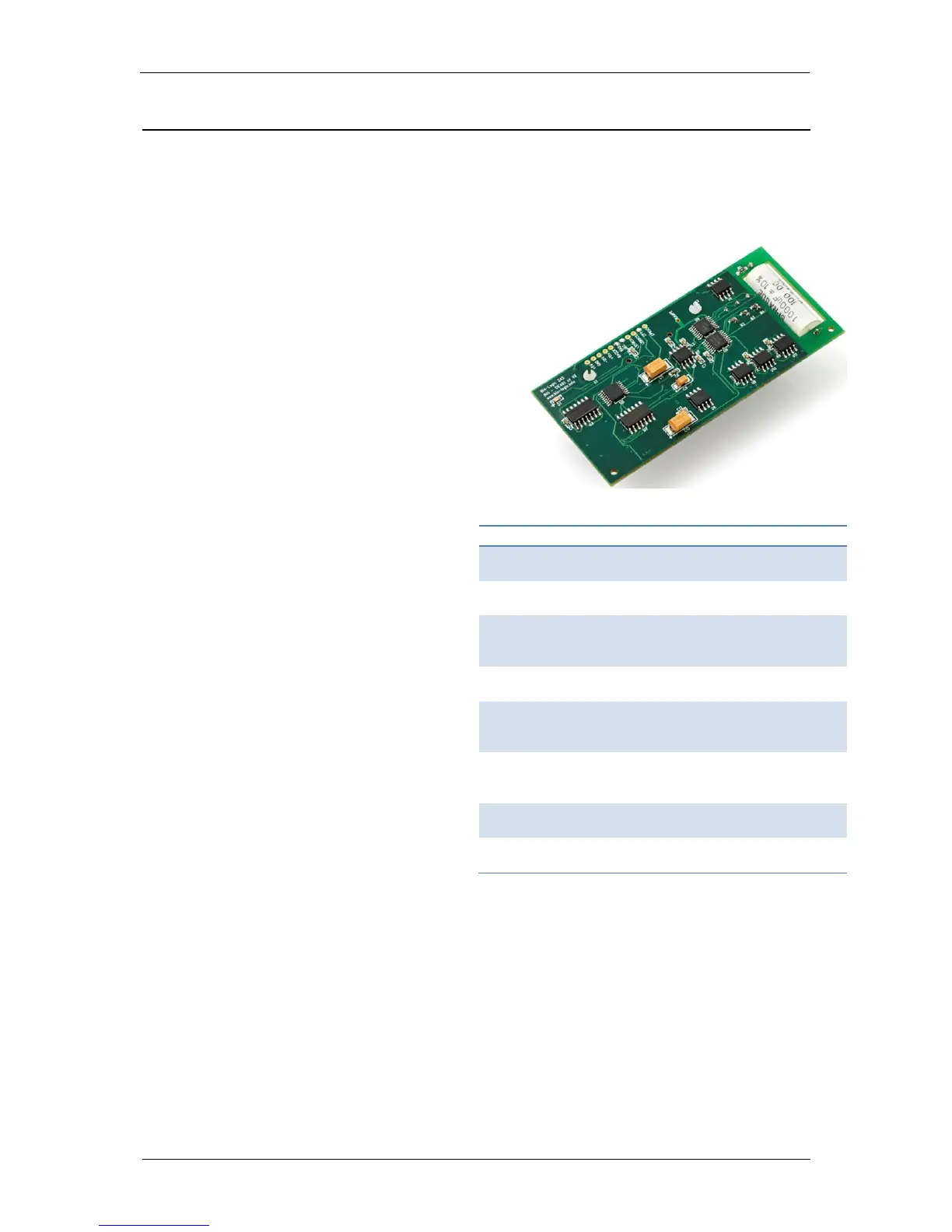
This option is an electronic board which
has to be plugged onto the
potentiostat/galvanostat board. It allows
users to apply a true linear voltage scan
(analog and not digital) to the cell.
The analog nature of the scan is critical in
several applications such as catalyst study
for fuel cell development or for voltammetry
requiring fast scan rate (to detect
intermediate species with short lifetime).
As the linear scan generator allows fast
scan investigation, hardware ohmic drop
compensation is also implemented in the
software. This correction is done
continuously by the hardware which is
much faster than the software
compensation. For example, we can
compare the standard and linear CV. Due
to the feedback loop, the software
compensation with the standard CV takes
around 100 µs while the hardware
compensation is about 100 times faster.
This option is compatible with ULC cable
and booster boards.
7.2 Isolation System (IS1)
It is used to keep a potentiostat totally floating even when it is connected to a grounded external
device via the auxiliary cable.
The auxiliary cable is connected to the potentiostat board using the DB9 (or SubD 9)
connector. Thanks to this cable, an external device can communicate with the potentiostat
either by sending/receiving digital triggers or sending/receiving analog signals. When the
auxiliary cable is connected to an external device, the potentiostat board becomes grounded
to the internal ground of the external device. Consequently, if the channel was initially used in
the floating mode, connecting it to the external device using the auxiliary cable makes it lose
its floating character.
 Loading...