45
E
we
= S1 - S2
E
ce
= S3 - S2
Notes:
CAUTION
Disconnection of the cell cable without switching off the instrument can damage the
electrometer located on the cable (either on the standard cable or on the ultra-low
current option)
WARNING
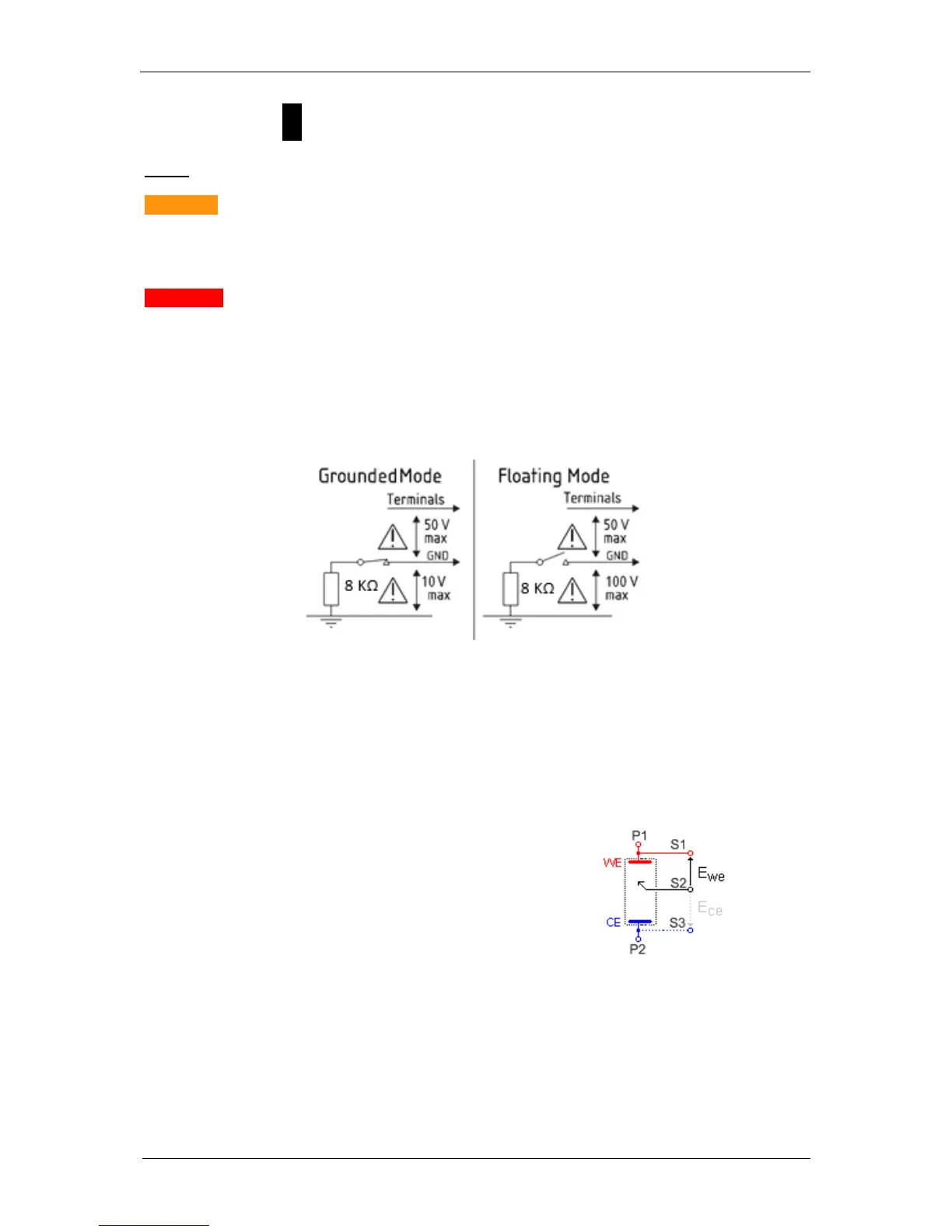
Voltage limits for standard and ULC cables:
- In Grounded mode: the potential between the grounded lead (black lead) and the
terminals should not exceed 50 V. The potential between the grounded lead and the
earth not exceed 10 V.
- In Floating mode, the potential between the ground lead (black lead) and the terminals
should not exceed 50 V. The potential between the ground lead and the earth should
not exceed 100 V.
Fig. 59: voltage limits in grounded and floating mode.
The current (defined in the positive direction) crosses the electrochemical cell from P1 to P2.
Three typical standard configurations are explained below.
5.2.2 Standard connection
5.2.2.1 Standard three-electrode connection
In the standard three-electrode connection mode
typically used in analytical electrochemistry or
corrosion experiments, the working electrode is
connected to S1+P1. The counter-electrode is
connected to S3+P2, and the reference electrode
is connected to S2.
 Loading...