11
Fig. 7: HCV-3048 back panel additional information.
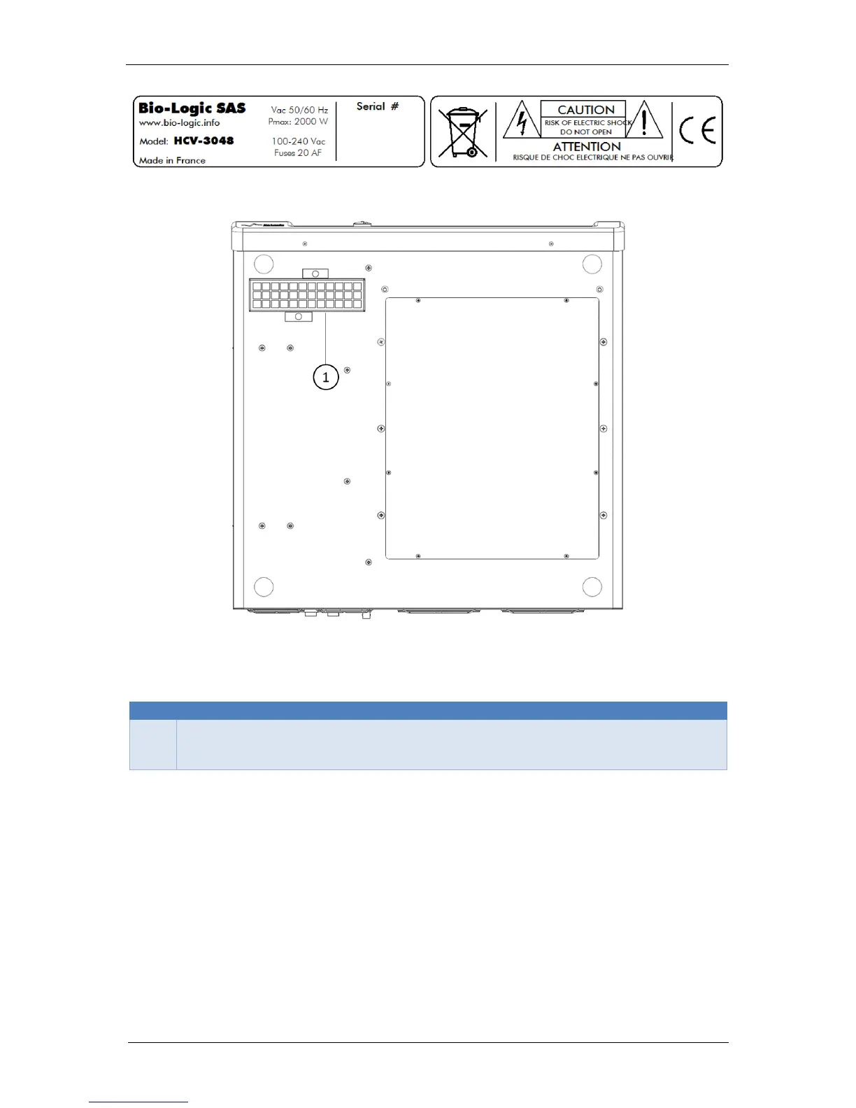
Fig. 8: HCV-3048 bottom panel.
Table 4: Description of the component of the bottom panel of the HCV-3048.
Bottom filter for power supply
This is where the air cooling the power supply is suck up. It has a filter that needs to
be cleaned and/or changed. See Chapter 9 Maintenance.
1.2 New board installation in an existing instrument
When a user orders new boards (channel board, low current board or a booster board), they
can install them themselves. The procedure for this operation is described in the corresponding
service note. With the newly provided boards, the latest software version must always installed.
This can be downloaded from our website. The board installation procedure consists of 4 steps:
1- Install the new software version on the computer and on the instrument firmware in
order to have the old unit and the new boards in the same software version.
2- Power off the unit and unplug it.
3- Install the new boards in the chassis, plug in the unit and power it on.
4- Calibrate the new boards with EC-Lab
.
 Loading...