MP 030 EL NM GB Copyright BIO-UV - 29/01/2009
Marque, Modèles et Brevets déposés - Produits exclusifs
Page 17
G. ALARM CONTACT (OPTION)
The pre-alarm and main-alarm faults are indicated by snap contacts on the monitor which are transmitted
to terminal strips (see the wiring diagram in order to identify them).
The snap contacts are normally closed. They open when respective alarms are active.
H. OPERATION OF THE 4-20MA OUTPUT (OPTION)
The 4-20mA adjustment must be realised:
- at the first installation of the reactor,
- at each calibrating of the UV sensor.
The 4-20mA adjustment must be realised only after the UV sensor calibration.
(See Chapter MANUAL OF THE MONITOR BIO-UV MIII)
The 4-20 mA output is the image of the UV-C sensor output not the image of the UV-C
% display on the monitor screen.
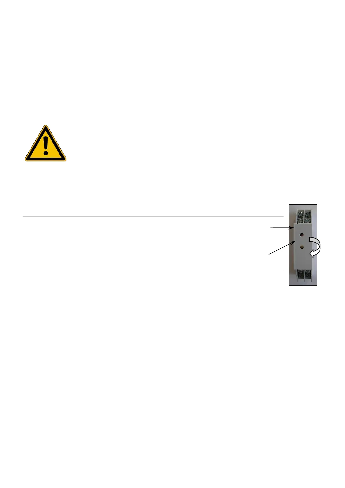
CALIBRATION OF THE 4-20MA OUTPUT:
1
Before the second step, you must realise the UV-C sensor calibration.
2
Turn the small screw clockwise
until the red LED lighting.
3
The 4-20mA output is calibrated at 100% of UV sensor.
Red
LED