KT-210-428
100
0
90
80
70
60
50
40
30
20
10
0
f [Hz]
I [mA]
2 4 6 8 10 12 14 16 2220
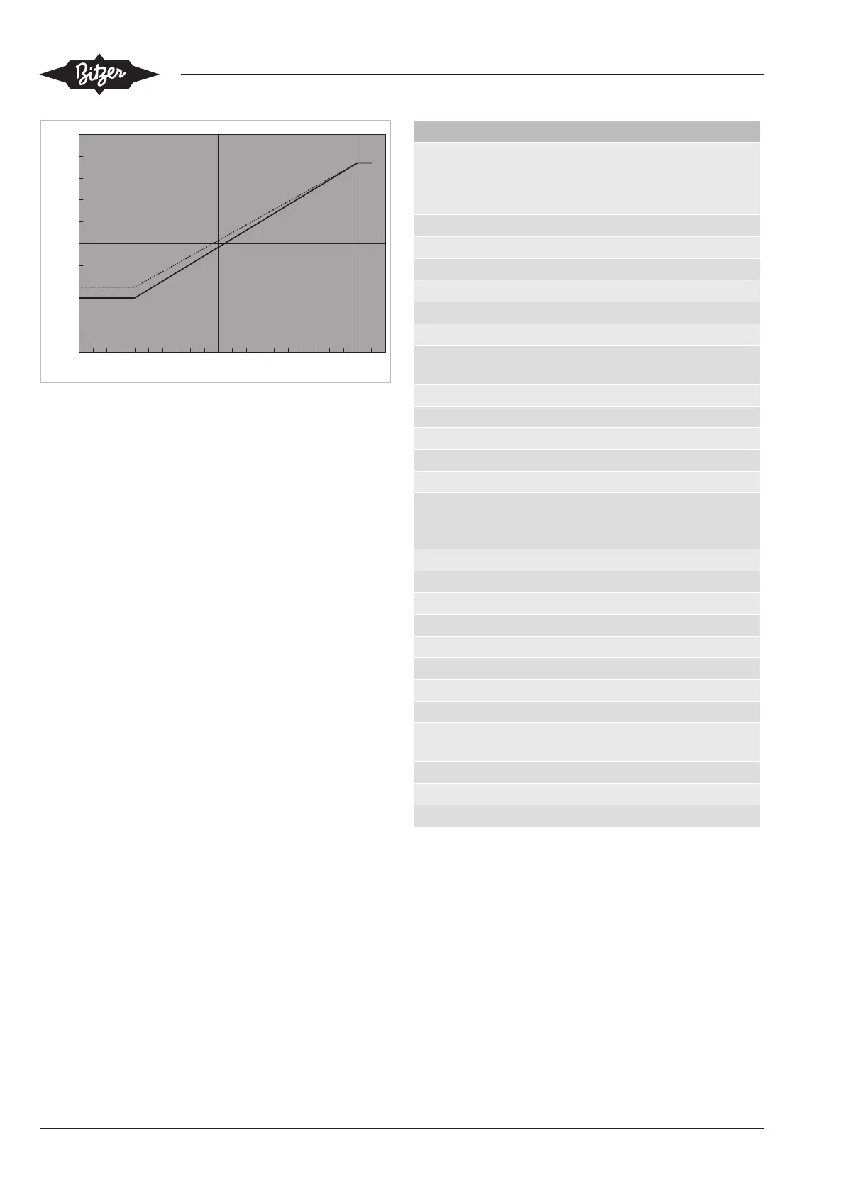
4 .. 20 mA
Fig.8: Control characteristic 4 .. 20 mA, dashed line 2-cylinder com-
pressor, continuous line 4-cylinder compressor
The FI automatically recognises the control character-
istic from the terminal connections. Further parameters
do not need to be entered.
Control range
The control range for the compressor frequency f is as
follows:
• 2-cylinder compressor: 30..87 Hz.
• 4-cylinder compressor: 25..87 Hz.
The compressor speed (frequency) is defined by the
control signal.
Standard control speed
• With frequency increase 50 Hz/s
• With frequency reduction 100 Hz/s
The control signal conversion is limited to these control
speeds. If high load variations are to be expected, it
may be necessary to program longer delay periods in
the superior controller (B3).
4.3 Schematic wiring diagram
Connect the compressor and the FI in accordance with
the schematic wiring diagram. Install the buttons S1 to
S4 in the switch cabinet.
The schematic wiring diagram shows a differential oil
pressure monitoring (option only for the compressors
4FE-5.F1..4CE-6.F1). Without such monitoring, the
Delta-PII and the components S3 and H2 can be omit-
ted. The main contactor K1 and the pressure switch F5
should in this case be installed in path 12 at the con-
nection 14 of the SE-B1.
Abbr. Component
B1 Control unit (cooling demand) or com-
mand for compressor start (release sig-
nal from the system controller) or con-
troller On/Off
B3 Controller for compressor speed
F1 Main fuse
F3 Control circuit fuse
F5 High pressure switch
F6 Low pressure switch
F12 Oil heater fuse
H1 Light "overtemperature" (motor and dis-
charge gas) and "oil supply fault"
H2 Light "oil supply fault"
H3 Light "collective fault"
H8 Light "fault FI"
K1 Main contactor
K8 Auxiliary relay FI
K2T Time relay "pause time" 120 s! Depend-
ing on the compressor, the pause time
can be significantly longer!
K4T Time relay "alarm delay" 5 s
M1 Compressor
N1 Frequency inverter (FI)
Q1 Main switch
R1..6 PTC sensors in motor winding
R7 Discharge gas temperature sensor
R8 Oil heater
S1 Control switch (on/off)
S2 Reset "overtemperature" (motor / dis-
charge gas) and "lack of oil"
S3 Reset "lack of oil"
S4 Reset "FI fault"
Y2 Solenoid valve "liquid line"
Tab.2: Legend
SE-B1: Protection device
Oil monitoring (option for compressor
4FE-5.F1..4CE-6.F1): Delta-PII
 Loading...